 Yaolong Liu
 Siyu Zhang1
- 1School of Aeronautics and Astronautics, Zhejiang University, Hangzhou, China
- 2School of Aeronautic Science and Engineering, Beihang University, Beijing, China
- 3China Helicopter Research and Development Institute, Jingdezhen, China
This study reviews tools and approaches developed at universities and institutes for conceptual and preliminary aircraft design. Problem, solution, and behavioral space covered by each tool are discussed and a categorization for the methods underlying the different disciplinary tools is proposed. Special attention is given to the search method, if any, embedded in or supported by each tool to explore the proliferation of Multidisciplinary Design Optimization (MDO) in aircraft design tools. The study shows that many tools are available but most are proprietary and none covers all the aspects of the conceptual and preliminary design process. MDO is only a small element in most of the tools. The review can be used for the formulation of requirements and necessities for future aircraft design tools.
Introduction
Aircraft design tools serve multiple purposes, ranging from design education support and aircraft conceptual design in industry, to exploration of ideas in innovation management. The objective of this paper is to identify and review the tools developed for and used in aircraft design research at universities and institutes as well as design tools commercially available. The term design tool in this context is defined as a coherent set of computer programs that allow a human user to select and/or define a set of design requirements (problem space), define or select an aircraft configuration (the solution space) both of which are used by the tool to size a set of design parameters belonging to the concept based on behavioral models (behavior space). For example, such a design tool would allow the user to specify requirements such as MTOW, required number of passengers, amount of cargo, required range for different payloads, and block speed. The user can select an aircraft configuration such as a tube and wing type aircraft and the tool than reports the required values for the parameters defining the selected configuration and reports the specification of the solutions. From this example it becomes clear that design tools can vary from very simple ones, only being able to address the basic elements of a simple design concept to tools that allow specification and analysis of novel configurations. To be able to review such apples and oranges a classification of the tools is proposed based on functionality and fidelity.
The review is intended to support the reader in the selection of tools that best fit the nature of the design problem at hand. A more specific secondary goal is to identify the tools that can support researchers in academia and industry with the selection of tools for use in Flightpath 2050 [1] related research, which requires airplanes flying in the year 2050 to reduce CO2 emissions with 75% or more compared to the airplanes of the year 2000. To achieve this goal, new technologies as well as novel aircraft concepts need to be developed. Electric or hybrid electric propulsion aircraft, active load alleviation technologies, boundary layer control technologies, bionic airframes and novel aircraft configurations such as blended wing body are examples of the solutions suggested for achieving the defined goals for future aircraft. A review and analysis of the new technologies for the design of future aircraft is presented by Liu et. al [2].
As the rapid progress of Multidisciplinary Design Optimization (MDO) methods in aerospace engineering (AGILE [3, 4] Openmdao [5, 6]), a last goal of the review is to discover the extent to which MDO have entered the conceptual and preliminary design tool world to be able to define future research and development in this area.
Classification of Designs, Design Processes and Tools
Aircraft design comes in many different flavors and a (limited) classification is needed to compare and compartmentalize the different tools. For this review we classify aircraft design in four categories:
• Type A: Derivative Design, example: new stretched version of an existing aircraft such as the design of a stretched Airbus A320neo.
• Type B: Configuration Fixed New Design: new aircraft to replace an existing, aging, class of aircraft models such as Boeing New Midsize Airplane
• Type C: Configuration Free New Design: new aircraft to answer new functional demands in an existing market such as MIT double bubble aircraft [7].
• Type D: Open New Idea: new concepts to develop new products for new demands or disruptively change solutions to existing demands such as GoFly for Personal Transport1.
• Type E: New Technology Development: new tools to develop new technologies in conjunction with new aircraft concepts, i.e., exploring new aircraft concepts with new technologies at a very low technology readiness level (TRL)2 [8].
To be able to assess the applicability of design tools for a specific aircraft design task the aircraft type also needs a classification. One of the more useful classification principles is functionality:
• Civil transport: passenger transport, cargo transport, leisure.
• Military: transport, fighter, bomber, reconnaissance, communication and relay.
• Civil safety and security: border patrol, firefighting, etc.
The aircraft design process is a mixture of integration/combinatory efforts on aircraft system level to find the best compromise to a list of competing requirements and subsystem design efforts when a new concept depends on new/modified solutions to subsystem requirements. This means that aircraft design is a multi-level exercise where choices on one level can instigate changes on other levels. This is well reflected in the V-figure (cf. Figure 1) from the Systems Engineering world [9]. The left leg of the V shows the flow down of requirement from Top Level (e.g., the aircraft level) all the way to part level. The right leg shows the solutions to the left leg requirements. Aircraft design requires travelling down left and right leg until all requirements are understood and complied to. The difficulty in design is that partial solutions themselves create requirements for other partial solutions and the V-Figure therefore cannot be used as a simple path starting from top left and ending top right. Iteration is the key word. The more freedom in the design process (Type A -> E) the more iterations and partial solution development are needed. This will also change the nature of the design tools. Where the designer can build on existing solutions for Type A designs and use statistical data of what is already out there, the design of a Type D will rely mostly on experimental design and physics-based modelling.
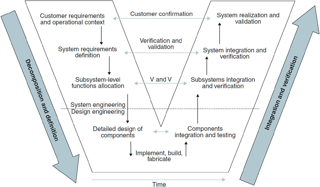
Figure 1. The V process model [9].
To be able to judge a design with respect to the functions and constraints in the requirements list an estimate of the design’s behavior is required. This is where the disciplinary tools come into play. For example, to fulfill the function “Provide Aerodynamic performance” tools/experiments are needed to quantify the lift, drag and aerodynamic moments on the aircraft as well as the dependence of these behavioral parameters on environmental conditions and system states. The type of tools/experiments that will be adequate for this task depends on the type of design and the confidence we can have in each of these tools/experiments. The “newer” the solution, the better it is to experiment with conforming prototypes. For derivative designs a computational approach or even a statistical approach with maybe some corrections based on simple experiments could be sufficient.
The disciplines considered in this review are (cf. Figure 2):
• Geometry
• Aerodynamics
• Structures and weights
• Stability and control
• Propulsion system
• Mission analysis
• Noise prediction
• Environmental impacts
• Systems
• Costs
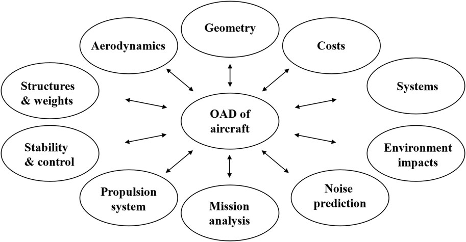
Figure 2. Major discipline of overall aircraft design (OAD).
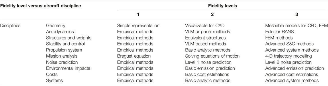
The tools available for each of these disciplines have been classified as well. For each tool the design behavior it can estimate as well as the fidelity with which the tool can estimate the behavior. A detailed description of the fidelity for each discipline is given in Section 6.
Last but not least is the functionality of the tool as a mimic of the design team efforts required to do design. That is: how do we feed ideas into the tool how do we control ideas and their modifications by the tool? This touched upon the knowledge acquisition and management by the tool. The input of ideas can be in an engineering parameter space using references to e.g., existing airfoils and subsystems or it can be in a 3D geometry space where a wing is defined as a geometric object which geometry can be manipulated by an Free Form Deformation (FFD) box [10]. The first method being very useful for Type A design, while the latter probably required for Type C and D designs. The manipulation of ideas can be by changing airfoil selection or, as already mentioned an FFD box. The most complete option being the use of Knowledge Based Engineering tools where principal building blocks are defined and grouped using ontologies. Manipulation of ideas can take place by manipulating the building blocks and/or the ontological relations. Level of complexity and investments associated with these different methods is very diverse and requires careful considerations when selection the design tool/method. Last item to be mentioned here is the way the idea input and manipulation interacts with the search algorithms (if any) and the disciplinary tools. Automatic work flow generation and execution based on a formal MDO problem definition being the most complete but often not required or possible. For each of the tools being reviewed the operational aspects will be discussed as well.
• Parameterization methods
• Formulation of design constraints, design variables, design objectives.
• Work flow manager of the design tool
• Integration strategy and architecture
• Data and design history storage
Note that a general MDO strategy for aircraft design was discussed by Kroo [11] and a comprehensive MDO architecture has been proposed by Martins et al. [12]. In general, the MDO problem can be categorized into Monolithic Architectures (most notably all-at-once problem) and Distributed Architectures [13]. According to [14], KBE can support robust parameterization of products with topological variation possibilities for optimization, which plays a very important role in advanced MDO. Examples for dealing with complex but subsystem level problems using KBE supported MDO can be found at ParaPy website3.
Aircraft and Subsystem Scope: Ways of Parameterizing
According to the goals of this review, i.e., supporting the reader in the selection of best-fit tools for general and specific aircraft design problems as well as discovering the future development direction of design tools towards MDO, we need to consider the space of options for each element based on the following information: type of aircraft, type of design, disciplines, subsystems, design team mimics. That means we have to consider the level of design constraints, i.e., which type of design it is. Based on the information available and the design requirements, we have to consider which components need to be taken into account (wing, fuselage, tails, engines, landing gears, etc.) at an aircraft level. Depending on specific design problems, particular attention has to be paid to what solutions/concepts are considered for each component, e.g., wing with sweep, taper, winglet, kinks, etc. Once the desired properties of/disciplines related these components can be derived from the aircraft level design behavior (e.g., weight, cost, range, speed, noise, etc.), we need to consider the component decomposition and parameterization. In the same time, a functional decomposition has to be taken into account, i.e., the methods and fidelity level for deriving component and aircraft level properties have to be considered.
Short History of Design Tools and Methods
Design of a new aircraft by integrating all these technologies and concepts discussed in the previous sections is a challenge. Since the 1980s, many computer supported aircraft design tools have been developed using the traditional aircraft design methodologies, such as those presented by Torenbeek 1982 [15], Anderson 1999 [16], Howe 2000 [17], Raymer 2012 [18], Sadraey 2013 [19], Sforza 2014 [20] and Gudmundsson 2014 [21]. Rentema [22] has carried out a survey on the computer-aided aircraft design tools in the developed before or around 2000, where most of pioneering design tools are out of updates and out of use. Very recently, Briggs has reviewed several aircraft design tools [23] and the integration approaches [24] based on recent AIAA technical committee’s conference bibliography.
However, due to the use of statistical and (semi) empirical methods, which are developed based on the past generations of the aircraft, the tools using traditional design approaches do not let the designers to easily apply those methods for the design of the future aircraft. On the other hand, novel approaches such as KBE supported MDO [13], artificial intelligence supported design [22], probabilistic model supported component-based shape synthesis [25] have shown promising possibilities to extend traditional design approaches. For developing new design methodologies and tools, the first step toward evolving the next-generation of aircraft design tools is to analysis the available tools to find their strong and weak points. This allows us to determine the requirements for developing the next-generation of the aircraft design tools.
Tool Scope
In this paper the aircraft design confines to the conceptual design and preliminary design phases. The conceptual design phase includes the process starting from a list of top-level requirements, setting the aircraft overall size and configuration, choosing the propulsion system, initial sizing of the main aircraft components, analysis of the design in terms of aerodynamics, structure and weight, propulsion, flight dynamics and performance as well as cost, refining the design until the top-level requirements are fulfilled. The preliminary design phase includes the design and optimization at component level, such as wing aerostructural analysis and optimization.
The scope of this paper is to review the available aircraft design tool and evaluate them based on the design methodologies used in them and their design abilities, i.e., which disciplines are included within the design tool and what methods are used for the disciplinary studies as well as for obtaining the overall aircraft behavior. As a design tool, it is also important to take a look at the deliverables of the tool (three projection view, full 3D model, database with performance data, etc.).
In the first part the methods we suggested to evaluate a design tool is discussed. Then the available design tools are presented and evaluated based on our suggested evaluation criteria. It should be noted that the focus of this paper is on the tools for designing civil transport aircraft. Though, some of the tools and methods summarized in the review might also be applicable for designing/sizing other types of aircraft such as military aircraft, general aviation, unmanned aerial systems, etc.
Methods for Evaluating the Aircraft Design Tools
As all tools have their own application scopes and limitations, the evaluation of aircraft design tools needs to be questions/tasks-oriented, i.e., what the requirements are, how much freedom we have, which kind of solutions we expect, what we need to know about the individual/global etc. A high level of consideration is essential for deciding the development of an aircraft design tool or choosing a tool for an aircraft design task. Here we suggest the following method, or questions, for evaluating aircraft design tools. In general computer aided aircraft design includes two main steps. In the first step the designers’ ideas should be somehow implemented into a computer program. The next step is to manipulate the ideas in an iterative way until the top level requirements are satisfied. Of course in order to manipulate (refine) the design different properties of the design should be obtained. Based on this steps we suggest four questions to evaluate an aircraft design tool (see Figure 3): How to put the ideas into computer? How to manipulate the ideas? How to get the properties/performance of desired entities? How to run the iterative process effectively? In the next part we discuss each of these questions in details.
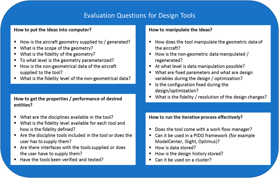
Figure 3. Top-level questions for evaluating aircraft design tools.
How to Put the Ideas Into Computer?
The first step to design an aircraft using computers, is to define the aircraft in the digital environment. It is critical that the aircraft should be defined a such a way that different components/subsystems can be explicitly analyzed and refined. To achieve this, the aircraft need to be parameterized using a component-based decomposition. As the overall aircraft sizing process needs to be carried out efficiently, the disciplinary studies have to be generated automatically based on aircraft geometry models. A unified and centralized aircraft data is essential for aircraft design especially when multi-disciplinary high-fidelity analysis methods are involved. In order to further evaluate this aspect of the aircraft design tools, the following sub-questions are suggested:
a. How is the aircraft geometry supplied to/generated by the tool?
In general, the geometry is parameterized using representative parameters or directly using CAD file if the design tool is built based on a CAD tool.
b. What is the scope of the geometry?
The aircraft geometry should include standard components such as wing, empennage and fuselage. It can also include more details such as high-lift devices, control surfaces, fairings, landing gear, engines/pylons.
c. What is the fidelity of the geometry?
The geometry fidelity is defined as follow.
• Low fidelity: Lowest level aircraft geometry uses global aircraft shape parameters (abstract design description [26]) such as wing span, aspect ratio, average thickness to chord ratio, etc., which is adequate for simple empirical/semi-empirical analyses.
• Medium fidelity: The second level geometry model defines the aircraft according to the outer mold-line (OML) of the aircraft to a degree sufficient for VLM/panel aerodynamic analyses or for simple structural analyses such as beam model [26].
• High fidelity: A high fidelity geometry is defined as watertight CAD such as NASA OpenVSP or meshable models for CFD [27] or FEA [28].
d. To what level is the geometry parameterized?
As the main purpose of the aircraft geometry parameterization is for sizing/optimizing aircraft for desired performance, it is important to define enough details based on the design analysis and optimization methods. For example, if a full CFD for aerodynamic analysis is performed, enough geometric details need to be available to allow the designers to prevent excessive pressure drag, detached flow etc. by modifying the geometry. It such a case defining the wing geometry only using planform parameters (span, sweep angle etc.) is not enough and at least the airfoil shape at various spanwise sections need to be parameterized as well.
e. How is the non-geometrical data of the aircraft supplied to the tool?
There are several types of non-geometrical data: component mass data, performance data, engine performance data, requirement and specification data, monetary data, emission data, etc. Depending on the focus of the design tool, some of the non-geometrical data can be simply hard coded (fixed) numbers, or define as inputs, or generated by a tool in the system.
Currently there are several common data format for storing both geometrical and non-geometrical data in XML format. Examples are the US CAFFE with an internal data structure and a persistent XML database [29] and the DLR CPACS [30] with an XML format common description for aircraft design.
How to Manipulate the Ideas?
The manipulation of ideas refers to how to consider the design process, which can be designer’s decision, a sequential sizing procedure, or a Multidisciplinary Design Optimization (MDO) process. Aircraft design is inherently an iterative process. However, the iteration can be performed in different ways. In general, two approaches are used. Sizing driven design and MDO driven design. In sizing driven aircraft design process, aircraft parameters are determined through iterative component sizing process based on top level aircraft requirements and specifications. However, in MDO driven aircraft design process, the whole aircraft design process is formulated as an optimization process, where all top-level aircraft requirements and specifications are formulated as design constraints, and the aircraft parameters such as geometry parameters are considered as design variables. Through MDO procedure, the aircraft parameters (design variables) are determined when the design objective(s) (such as fuel burn/or DOC) is/are minimized.
Independent of the method used for iteration, the following aspects should be considered for evaluating the data manipulation capabilities of a tool.
a. How does the tool manipulate the geometric data of the aircraft?
For example, does the tool regenerate the aircraft geometry based on modification of the parameters like airfoils, span wise data etc., or a flexible geometry manipulation method such as free form deformation is used, in which the base geometry can be perturbed based on the changes in the geometrical parameters, without a need for regenerating the whole geometry.
b. How is the non-geometric data manipulated/regenerated?
The non-geometric data can be manipulated (updated), for example, via either simple equations or sub-modules of the design tool or external tools connected to the design tool.
c. At what level is data manipulation possible?
Similar to the fidelity level of the parameterization, part 6.1.c, the manipulation can be done in different levels of fidelity.
d. How does it specify that what are fixed parameters and what are design variables during the design/optimization?
Despite the fact that all aircraft parameters can be set as design variables, in most cases only several important parameters are chosen to be varied during the design optimization due to computational constraints. Wing planform parameters such as reference area, aspect ratio, taper ratio, sweep, etc. are the most common design variables chosen for design optimization. In some occasions, flight conditions such as flight speed and altitude are also chosen as design variables. As pointed out by Drela [31], most of the design practices decouple the aircraft design optimization and the engine optimization, which leads to (false) sub-optimal solutions. Therefore, to achieve the true optimal solution, the aircraft and engine parameters have to be considered simultaneously, see Figure 4, where FPR represents for fan pressure ratio, Tt4 for turbine inlet temperature, W/S for wing loading, M∞ for free-stream Mach number.
e. Is the configuration fixed during the design/optimization or is the tool able to explore/generate multiple concepts based on a single set of requirements?
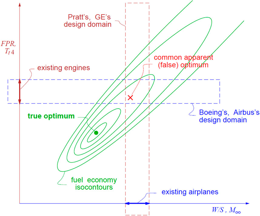
Figure 4. Domain-restricted optimum and true global optimum [31].
Changing the configuration during the design optimization is extremely important for open new designs (Type C designs). If the design tool keeps the configuration fixed, design and optimization can only make moderate improvements within a constraint design space. The advantage is that the narrow design space can significantly save the optimization time if the initial configuration is correctly chosen. However, being totally dependent on the designer’s/export’s initial choice can lead to a high risk of missing the revolutionary design possibilities.
f. What is the fidelity/resolution of the design changes that can be made by the tool during design/optimization?
In part 6.1.c, the level of design manipulation is discussed. However, the effect of each change can be captured with different resolutions. This resolution depends on both the disciplinary tools as well as the overall design framework. For example, investigating the impacts of adding advanced leading edge devices to an existing aircraft, not only requires reliable aerodynamic and structure analysis for high-lift systems, but also needs aircraft level sizing and computing the snowball impacts. Otherwise, the overall impacts of integrating new technologies cannot be correctly estimated.
How to Get the Properties/Performance of Desired Entities?
In order to assess the design and get the properties or performance of desired components, analysis methods and tools need to be applied. The criteria of choosing correct/proper analysis tools directly depends on the design goals and questions. As such, the tool should have sensitivity to the question we want to address with acceptable calculation time and complexity. In this subsection the analysis methods for individual disciplines are reviewed. Before that, it is important to take a look at the definition of fidelity levels for each analysis disciplines.
According to Nickol [32], Price et al. [33] and Rizzi et al. [28], the individual disciplines (aerodynamics, structural analysis and weight estimations, noise, emissions, stability & control and geometry generation) can be categorized as low fidelity, medium fidelity and high fidelity. In this study, we modify the fidelity levels to 1 to 3 and extend the categories into 9 disciplines for better comparisons (see Table 1). In the following part, the tools and methods for different disciplinary analysis are reviewed and discussed.
Aerodynamics
For conceptual and preliminary aircraft design, the fidelity of aerodynamic analysis can be described as follows:
1. Low fidelity: Low fidelity aerodynamic analysis uses empirical and semi-empirical methods and existing databases such as Datcom [34]. As low fidelity aerodynamic analysis takes advantage of statistical data of existing aircraft, it can give quite good predictions for conventional configurations. So it is mostly used for derivative designs, where much correction data is available for building up reliable first principle models. In general, the low fidelity aerodynamic analysis only incorporates several global aircraft and flight parameters, such as wing aspect ratio, mean aerodynamic chord, thickness to chord ratio, sweep angle, Reynolds number and Mach number.
2. Medium fidelity: The second level of aerodynamic analysis includes physics-based methods based on potential flow theory, that assumes the flow is incompressible and irrotational. Two typical methods based on the potential flow theory are the vortex lattice method (VLM) and the panel methods such as XFOIL [35] for 2D analysis and PANAIR [36] for 3D analysis. The basic VLM neglects thickness, camber and viscosity impacts and extended VLM such as AVL tool [37], Tornado [38] and DLR LiftingLine (DLR LL) [39] can usually include the thickness influence. Via proper corrections, the medium fidelity aerodynamic analysis can give good predictions for a wide range of design spaces. Such analysis are also sensitivity to low fidelity geometric parameters such as wing planform parameters [40].
3. High fidelity: The third level aerodynamic analysis utilizes Euler equations or Reynolds Averaged Navier–Stokes (RANS) equations. The Euler equations can give reasonable predictions of transonic flow and still holds the inviscid assumption. While the RANS method can capture the viscous influences. Due to the high calculation time requirements as well as the challenge of automatic mesh generation from geometry to CFD solver, it is still not very often to have Euler or RANS equations implemented for conceptual aircraft design. Currently, surrogate modelling is one possibility to enhance the fidelity of analysis without a high penalty on the computational cost [41].
Structure and Weights
Similar to aerodynamic analysis, the methods of structural and weight analysis are also discussed in terms of fidelity level.
1. Low fidelity: Low fidelity structure and weight analysis applies empirical and semi-empirical methods derived from existing aircraft weight databases. In general, the empirical methods are regressions of principle geometrical parameters and overall aircraft mass parameters. As such, the statistical-based regressions are very sensitive to the reliability of the applied weight database and are limited to very narrow design space. For new configurations or derivative designs with significant alterations, historical data based low fidelity methods might give unreasonable predictions. Note that this level of structure and weight analysis also refers to Class I and Class II weight estimation [42].
2. Medium fidelity: The second level structure and weight analysis use physics-based methods based on equivalent structures. This fidelity level analysis is also known as Class II and 1/2 methods [42]. The medium fidelity structure analysis decomposes the aircraft components into different parts. By estimating the required materials to carry critical loads, the total weight of the primary structure can be quantified. It has to be noted that some corrections for the weight of secondary structure such as control devices are still necessary [42]. The FAME-W (Fast and Advanced Mass Estimation Wing) developed by Airbus [43] is a typical example of such class of analysis.
3. High fidelity: Using finite element analysis (FEA) to calculate the primary structural mass requires detailed load cases, compatible geometry model of the aircraft structure including structural details such as cross-sectional shapes of spars, ribs, and skins. In addition, correction methods are still necessary for estimating the secondary structural weight that cannot be modelled in a FEA. Typically, the aero-elastic effect [44] is also included. A good example for high fidelity structure code is the Boeing code for Wing Multidisciplinary Optimization Design, or WingMOD [45]. The work of Perez at al. [46] also applies FEA for structure analysis in the context of aircraft design.
Stability and Control
The stability and control analysis for conceptual/preliminary aircraft design is not considered in details in many design cases (see, EU FP6 [47, 48]). As the stability and control analysis is directly dependent on aerodynamic derivatives, the fidelity levels are comparable (see, Chudoba et al. [49]).
1. Low fidelity: The low fidelity stability and control analysis uses semi-empirical methods (such as USAF Datcom [34]), which is strongly dependent on historical aircraft data.
2. Medium fidelity: The second level of stability and control analysis methods uses the derivative data from medium fidelity aerodynamics studies.
3. High fidelity: The third level of stability and control analysis methods uses the derivative data from high fidelity aerodynamics studies.
Propulsion System
Various computational methods have been developed to facilitate propulsion system calculations and simulations required for aircraft design. The methods of propulsion system modeling are also discussed in terms of fidelity level.
1. Low fidelity: The low fidelity aircraft propulsion system modeling uses semi-empirical methods [50, 51] or rubber engine data.
2. Medium fidelity: The second level of propulsion system modeling uses one-dimensional thermodynamic cycle analysis [52], where Gas Simulation Program (GSP) [53, 54] developed by the National Aerospace Laboratory of the Netherlands (NLR), Numerical Propulsion System Simulation (NPSS) [55], GasTurb [56].
3. High fidelity: The third level of propulsion system modelling usually depends on 3D flow and/or chemistry simulations [57–59].
In addition to traditional gas-turbine engines, there is growing interest in electric propulsion and hybrid propulsion system, which also calls for method development. Electric propulsion system modeling consists of not only the methods abovementioned, but also including other electric systems, such as electric motor [60–68] and battery [69–73].
Mission Analysis
Mission analysis are divided into the following three categories.
1. Low fidelity: Lowest level of fidelity for mission analysis uses Breguet equations to calculate the range and endurance of cruise flight while the rest of flight (taxi-out, takeoff, climb, descent, landing, taxi-in, and reserve flight) is calculated based on empirical data or corrections, such as the ones presented in Eurocontrol BADA [74] or Engineering Sciences Data Unit (ESDU) [75].
2. Medium fidelity: The second level of mission analysis considers aircraft as a point mass and uses the equations of motion to describe the whole flight procedure. Note that the detailed mission analysis requires corresponding aerodynamics and engine performance data for each flight condition (flight speed and flight altitude). Examples of medium fidelity mission analysis tools are the FLIGHT program developed by Filippone [76] for comprehensive analysis of transport aircraft flight performance and the APP (Aircraft Performance Program) tool developed at ALR Aerospace [77].
3. High fidelity: For a high fidelity mission analysis the full flight mission is described by the equations of motion (3 DoF or 6 DoF) and the inputs for iterative mission solutions including not only detailed aerodynamic polars but also comprehensive engine performance data from tools such as NASA Glenn’s Engine Performance code (NEPP) for engine performance [78] or NLR engine performance tool: GSP V.10 (simulation tool for gas turbine engines with graphic interface [79], or GasTurb software for engine performance [80]. An example of such mission analysis is the MICADO mission study tool [81].
Noise Prediction
Figure 5 from Filippone [82] illustrates the needs and applications at several level for aircraft noise predictions. It has to be noted that the category is quite high-level that does not show a component level fidelity diversity. A more detailed overview of airframe noise estimations is given by Zhang et al. [83]. Here we again categorize the noise prediction into three levels of fidelity:
1. Low fidelity: Pure empirical and statistic methods for predicting noise such as FLULA24, Integrated Noise Model (INM)5 and SIMUL at the DLR [84].
2. Medium fidelity: medium fidelity acoustic analysis uses semi-empirical methods for jet, fan, and airframe noise modeling, such as NASA Langley’s Aircraft Noise Prediction Program (ANOPP) [85], the ILR Noise Simulation and Assessment module (INSTANT, a parametric aircraft noise simulation module developed in recent years at RWTH Aachen University) [86], and the Parametric Aircraft Noise Analysis Module (PANAM) developed at the DLR [87]. Most of these tools are also able to carry out assessment in sound quality metrics of loudness, tonality and sharpness.
3. High fidelity: This level of noise analysis includes numerical methods using Computational Aero-Acoustics (CAA), especially for high lift wings and jet noise, fans, duct acoustics. A summary of NASA aircraft noise predictions is given in [88].
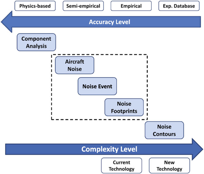
Figure 5. Nosie predictions at different levels in terms of accuracy and complexity [82].
Environmental Impacts
Assessment of environmental impact of a design was not initially not included in many design tools. However, as shown in Figure 6, the aircraft emissions have not negligible effect on the climate change. The need for the design of green aircraft makes it necessary to include an environmental impact analysis in an aircraft design tool. The methods for analysis of environmental impacts of an aircraft are categorized into the followings:
1. Low fidelity: Statistical data and pure empirical methods are used for emission estimation directly from fuel combustion process in aircraft engines. Emissions such as CO2, CH4, short-lived species (H2O, O3, soot, sulfate), contrails and cirrus are mainly considered.
2. Medium fidelity: This level of analysis include physics based as well as semi-empirical methods for measuring both direct release of chemical species as well as indirect climate change impacts (average temperature response). Examples of such methods are liner climate models [89], time varying normalized radiative forcing (RF) [90] and lifetime average climate impacts [89].
3. High fidelity: For high fidelity analysis of environmental impact of a design, climate-chemistry models for the predictions of aviation climate impacts are used.
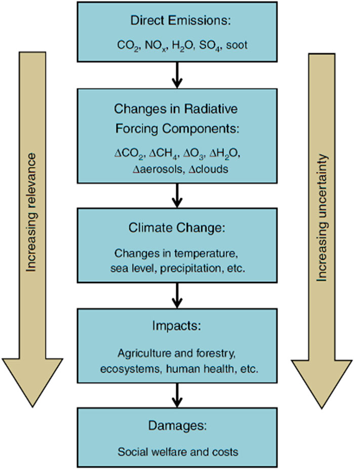
Figure 6. Aircraft climate change due to the release of chemistry species [89].
Systems
In conceptual and preliminary design phases a detailed design of different aircraft systems may not be necessary. However, some aspects of the systems such as weight and power requirements are needed to be estimated. The following methods are used for such a purpose:
1. Low fidelity: Statistical data and pure empirical methods are used to estimate systems’ masses, in which regressions are built up in relation to typical aircraft parameters such as MTOW [17], number of passengers [91].
2. Medium fidelity: Semi-empirical methods are used to estimate system masses and power input/output [92].
3. High fidelity: Detailed modelling of sub-system mass, power input/output during the flight missions, such as the methods of Liscouët-Hanke [93] and Koeppen [94].
Costs
Cost analysis is an extremely important part of an aircraft design process, as the cost is a key parameter determining the success or failure of a design! However, achieving a good and reliable cost estimation is quite challenging. Cost estimation can only be performed using statistical and empirical methods, as there is not physics behind the cost analysis! Therefore, categorizing the cost analysis is done based on the different cost components that are estimated in a design tool.
1. Low fidelity: Only direct operating costs (DOC) is estimated [95].
2. Medium fidelity: both DOC and recurring costs (RC) are estimated such as NASA RC Method [96].
3. High fidelity: The whole life-cycle cost (LCC) estimation is performed [97].
How to Run the Iterative Process Effectively?
Considering the design as an iterative process, the following questions are suggested to evaluate the efficiency of the iterative process:
a. Does the tool come with a work flow manager?
Working with a work flow manager makes the design process clearer which also provides a basis for treating the design problem as an MDO problem via only interacting with the work flow manager.
b. Can it be used in a PIDO (Process Integration and Design Optimization) framework?
A PIDO such as ModelCenter®, iSight®, and Optimus® can significantly ease the operation of the optimization problems, such that the designers can focus more on the aircraft related problems instead of spending much time and effort on making the MDO environment work. Alternatively, design tools can have their own MDO environment [24].
c. How are the data and the design history stored?
The storage of design data and design history data plays an important role especially when it comes to cases involving many disciplines and many iterations. For example, using a center aircraft database (e.g., DLR CPACS) for data exchange of disciplinary analyses can largely reduce the interfaces of different disciplines, thus increasing the efficiency of MDO process [98].
d. Can it be used on a cluster?
MDO based design methods were in the past (and mostly till now) more component/discipline oriented, i.e., only several disciplines are incorporated [99]. The full design space exploration in many cases are computationally too expensive. The capability of running the optimization on a computer cluster can significantly reduce the calculation time which enables exploring larger design spaces with more design variables accounted, or enables higher fidelity disciplinary analysis that takes longer time.
In this section of the paper different aspects of an aircraft design tool is discussed. In the next section, a review of the existing design tools is presented. In order to evaluate each tool, the method presented in this section is used.
Existing Aircraft Design Tools
Since 1970s, numerous overall aircraft design (OAD) programs have been developed at various universities. However many of them are not operational any more [100]. In this section, a selective of presentative OAD tools developed at NASA, DARcorporation, Raymer, Stanford University, MIT, RWTH Aachen, TU Braunschweig will be reviewed and discussed. For better overview, a full list of OAD tools is given in Supplementary Appendix SA.
NASA
In addition to the ACSYNT [101], that is not often used in the community any more, the Layered and Extensible Aircraft Performance System (LEAPS), the Intelligent Synthesis Environment (ISE), and the CAD tool OpenVSP [102], the most popular aircraft design tool developed at NASA is the Flight Optimization System (FLOPS) software [103]. FLOPS enjoys widespread use in NASA collaborations, with its capability validated in studies like the FLOPS vs. Pacelab APD comparison. FLOPS offers a systematic design approach with parameterized aircraft geometry definitions that can be transferred to OpenVSP for enhanced CAD and detailed analyses. Its design variables and constraints support thorough optimization, and its performance assessment modules cover a wide range of fidelity across disciplines. It uses semi-empirical methods for aerodynamics, structure and weight estimation (with special consideration for unique configurations [104]), noise calculations using established methods [105], stability, and control assessments. Emissions and systems analysis also employ semi-empirical methods, while mission segments are meticulously simulated. Its engine module can integrate with NPSS for performance data [106], and it boasts detailed cost estimation modules. FLOPS operates within a PIDO framework and is suited for cluster computing, with design data presumably stored in separate text files, though specifics on data storage are not detailed [103, 107].
Advance Aircraft Analysis
Advanced Aircraft Analysis (AAA) is a comprehensive tool developed by DARcorporation, building on the foundations set by Prof. Roskam. It provides an interactive, sequential sizing-based design process without built-in optimization features. Users interact with the software to define initial low-fidelity geometrical and non-geometrical data, selecting global configurations such as wing type, tail, canard, control devices, and engine specifics. AAA has been validated across numerous research and industrial endeavors [100]. The tool applies semi-empirical methods for analyzing aerodynamics, structure and weight, and stability and control. While it lacks noise and emissions calculations, it features a mission analysis module employing Breguet equations and a statistics-based systems analysis module. Engine performance is assessed using statistical methods, and a comprehensive module provides estimates for operating and life cycle costs. AAA’s geometry is parameter-based, suitable for low-fidelity studies but not directly applicable to external design or high-fidelity analyses. It operates outside of a PIDO framework and is not designed for cluster computing, focusing instead on a user-driven, iterative design approach without optimization.
Raymer’s Design System
Raymer’s Design System (RDS), created by Daniel Raymer and grounded in his aircraft design textbook [18], is a versatile tool that caters to various types of aircraft design, from advanced fighters and tactical UAVs to civil transport aircraft [108]. RDS allows users to generate and manipulate low-fidelity aircraft component geometries, such as wings, tailplanes, and fuselages, with provisions for creating new components and editing existing ones via its design layout module (DLM) [108]. While the professional version of RDS features optimization capabilities with eight design variables, the configuration remains static throughout the design process. Performance calculations in RDS are completed using low-fidelity modules for aerodynamics (employing semi-empirical analyses like USAF DATCOM), structures and weight (via empirical and statistical methods), and stability and control (with semi-empirical methods). Mission analysis is conducted using 3-DOF trajectory equations for improved accuracy, whereas system-wide performance and costs are estimated using statistical methods. For geometrical definitions, RDS uses the super conic surface component design method with 4th degree Bezier polynomials and allows for CAD exports through its DLM [80]. Though the professional version has optimization capabilities, RDS does not appear to be used within a PIDO framework or on clusters. Throughout the sizing and optimization process, data is stored in an “Aircraft Data File.”
Stanford University
The PASS tool, initiated by Prof. I. Kroo in the 1980s [109], implements decomposition-based MDO strategies [110, 111] for aircraft design, providing fast and efficient conceptual and preliminary design analyses. Its usage spans a variety of studies, from climate impact assessment [29, 89, 90, 112, 113] to new technology integration [114]. PASS manages geometry generation and modification with a focus on global planform parameters. It handles numerous design variables and constraints, as indicated in recent updates to optimize complex configurations [114]. Component performance analyses use multiple fidelity methods, interfacing with tools like ANOPP [115] and LinAir [116] for aerodynamics and noise evaluation, respectively. Mission analysis follows a segment-based approach, and emissions are analytically assessed. The tool’s optimization process involves sequential quadratic programming within a PIDO framework, and data is handled in an ASCII database with visualization capabilities for iterative changes [110]. Recently Stanford’s Aerospace Design Lab has gradually transferred to SUAVE, an aircraft design tool created by Stanford’s Aerospace Design Lab, excels in multi-fidelity analyses of various aircraft and propulsion systems [91, 117] It is Python-based, emphasizing flexibility in optimization and analysis rather than initiating design from base requirements. Capable of handling complex vehicle models, SUAVE integrates design variables optimization within a PIDO framework using tools like pyOpt and SciPy. It effectively manages data and supports detailed aerodynamics and performance evaluations, although it lacks emission calculations [91, 118, 119].
MIT
TASOPT is a Transport Aircraft System OPTimization tool from MIT designed for conceptual aircraft design within the NASA N+3 project, focusing on tube-and-wing configurations [120]. It integrates advanced airframe and engine technology advancements into the design process, including high bypass ratio turbofan engines and novel materials. TASOPT allows for detailed customization of aircraft geometry and engine parameters. It follows a nested iterative optimization process compatible with a PIDO framework, using genetic algorithms and Monte Carlo methods for multi-objective optimization [121–126]. Notably, TASOPT has contributed to the design of the MIT double-bubble D8 aircraft for NASA Subsonic Fixed Wing Project and has been expanded with newer methods like geometric and signomial programming for aircraft and engine design optimization [122–126]. Figure 7 shows the organization of TASOPT operation.
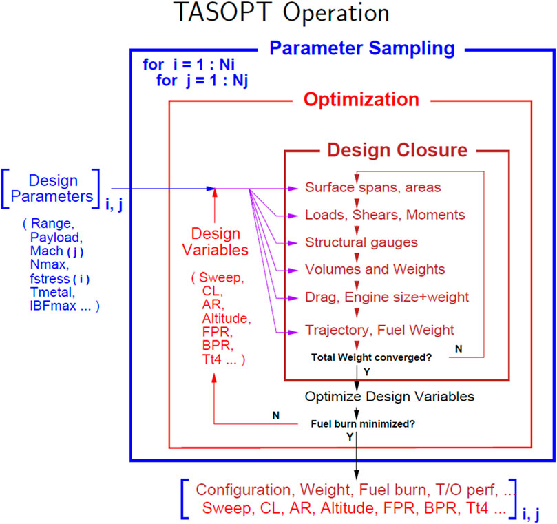
Figure 7. Organization of TASOPT operation [31].
TU Braunschweig
The Preliminary Aircraft Design and Optimization Program (PrADO), established at Braunschweig University of Technology, specializes in detailed modelling for comprehensive structure analysis and has been utilized in numerous research projects for both conventional and unconventional aircraft designs [127–131]. PrADO is recognized for its application in the design of a short takeoff and landing aircraft with active high lift systems, contributing to the SFB 880 project [130]. PrADO features a meticulous geometry definition covering standard components and detailed aspects like cabin arrangements and primary structures, all managed within a data management system (DMS) supporting high-fidelity analyses. The design process comprises a sequential sizing procedure with optimization for wing planform parameters, while overall configuration remains unchanged during the process. A suite of interdisciplinary analysis models validates PrADO’s performance, as demonstrated in projects like SFB880 and EU FP5 VELA [130]. PrADO incorporates various analytic methods for aerodynamics, structure and weight assessments, stability and control, and engine performance, although it lacks emission calculations. Mission analysis is conducted via equations of motion, and direct operating costs can be estimated. With its iterative sizing and optional optimization post-convergence, PrADO stores data in its database and design history in ASCII files, capable of running parallelized operations on clusters [131]. Figure 8 shows the PrADO modeling.
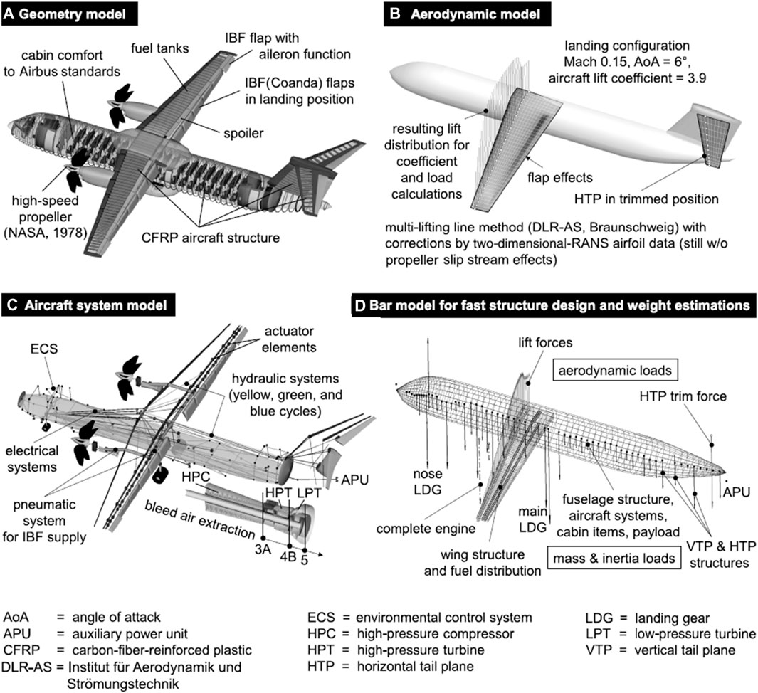
Figure 8. PrADO modeling for the assessment of the new aircraft configuration with high-lift devices [132]. (A) Geometry model, (B) Aerodynamic model, (C) Aircraft system model, (D) Bar model for fast structure design and weight estimations.
TU Braunschweig’s new aircraft design framework evaluates the energy efficiency impacts of cutting-edge technologies like active flow control on passenger aircraft, suitable for both conventional and blended wing body designs [132, 133].
RWTH Aachen University
RWTH Aachen University’s MICADO is an object-oriented software for aircraft design with XML-based parameterization, applicable to derivative and white sheet designs. It incorporates a wide range of applications, from fast design space exploration to assessing technology integration impacts on aircraft systems [134, 135]. MICADO produces detailed component geometry that can be exported for advanced visualization and analysis, storing various design and performance data within the adaptable AiX format. Geometry modifications primarily affect wing and tail planform parameters, and the tool’s reliability is proven through its use in the CeRAS reference aircraft program [136]. It integrates modules for aerodynamics, structure, noise, stability, emissions, mission analysis, and engine performance, supporting cost estimation as well. Optimization is executed via a workflow manager with potential for MDO studies, storing the design history separately for possible parallel run on clusters [136–138]. Figure 9 shows the design data flow and methodology of MICADO software.
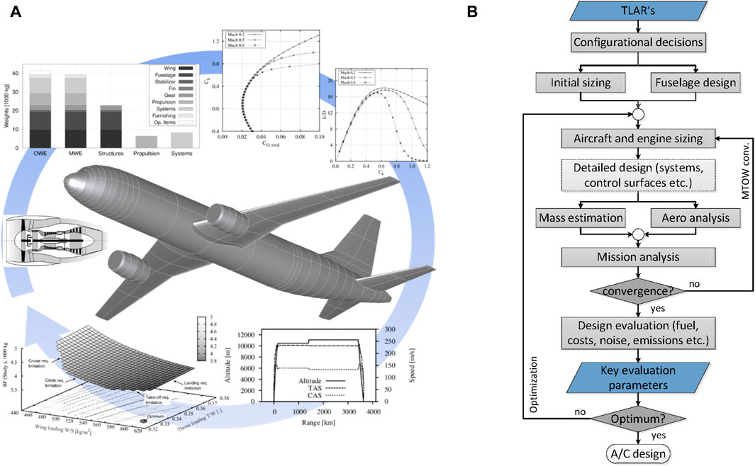
Figure 9. Design data flow and methodology of MICADO software [134, 136]. (A) Graphic view, (B) Flow diagram view.
Other Tools
In addition to the tools described above, there are other notable aircraft design tools available such as CADLab developed at Linköping University [139–141], the Computerized Environment for Aircraft Synthesis and Integrated Optimization Methods (CEASIOM) developed at the KTH [142–145], Initiator developed at TU Delft [146–150], pyACDT [151, 152] developed at the University of Toronto, the Aircraft Design and Analysis Software (ADAS, a JAVA programmed tool suite for conceptual/preliminary aircraft design) [153, 154] developed by the Design of Aircraft and Flight Technologies Research Group (DAF) at University of Naples and VAMPZero [155] developed at the DLR, and Fixed-wing Aircraft Sizing Tool developed by ISAE-SUPAERO and ONERA [156].
In addition to the aircraft design tools mentioned above, one notable framework is Environmental Design Space (EDS) developed at Georgia Institute of Technology (mainly the ASDL). EDS is a systems engineering oriented tool for aircraft design [9], see Figure 10. The EDS was initially developed with U.S. Federal Administration Office of Environment and Energy for specifically for assessing the aircraft level noise and emissions [158]. The vehicle modelling uses either NASA FLOPS code [158] or the recently developed Rapid Airframe Design Environment (RADE) is developed at the ASDL [159].
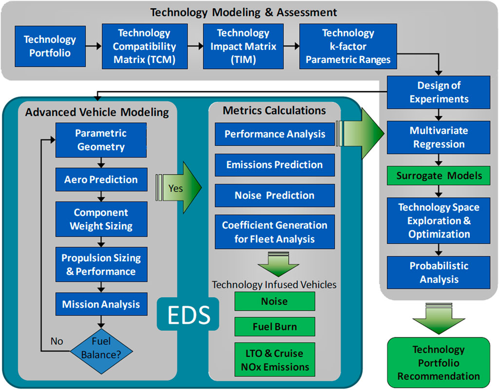
Figure 10. The overview structure of EDS centered system approach for aircraft design at the ASDL [157].
A Summary in Terms of Application Scopes, Fidelity Levels and MDO Levels
In this section, a summary of existing aircraft design tools and environments is given. In the beginning, the application scope for each aircraft design tools are compared. In total, we categorize all the design capabilities of the reviewed tools into 7 groups, in which the subsonic/transonic civil transport aircraft have been further divided into tube and wing (TAW), blended wing body (BWB) and strut-braced wing according to the aircraft configurations.
The indicators of MDO level are considered with the following criteria (cf. Figure 11). Figure 12 shows a summary of aircraft design tools in terms of fidelity level versus MDO level. Note that the horizontal axis MDO is loosely defined according to the capability of MDO studies using the approach proposed in [160]. For design variables, the number of design variables, whether design variables covering different disciplinary parameters, whether design variables coupling flight parameters, whether both engine and airframe parameters considered simultaneously; For design objective, whether one single objective defined or bi-objectives or multiple objectives pursued for design optimization. The fidelity level is roughly indicated by an arithmetic mean fidelity of the most significant/representative 9 disciplines selected above. Note that for the same order calculation methods, those with more components or sub-components included are considered as higher fidelity.
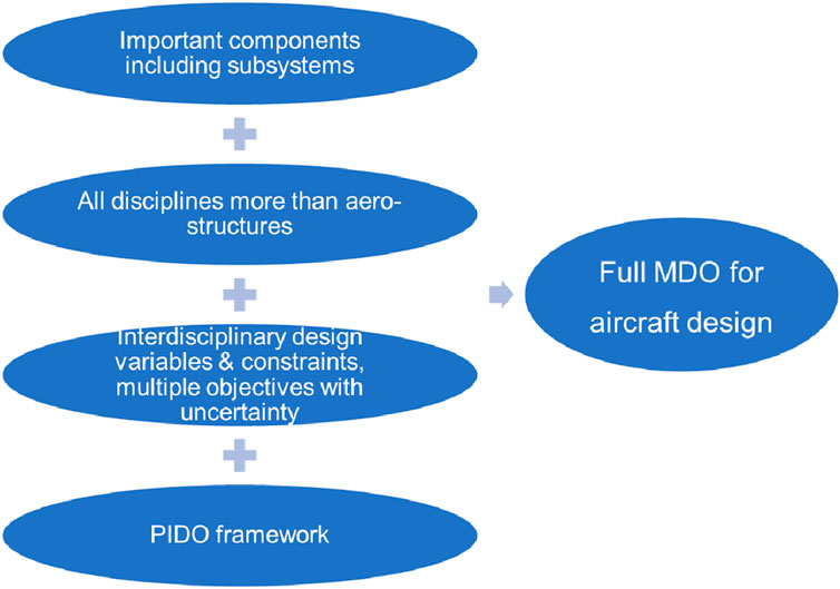
Figure 11. Proposed full MDO for aircraft design based on four evaluations questions.
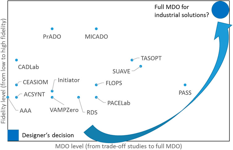
Figure 12. Summary of aircraft design tools (fidelity level versus MDO level).
Development Indications for Aircraft Design Tools and Methods
According to the review, most aircraft design tools do not cover all the important disciplines and some have only a limited number of disciplines such as aerodynamics and structures (e.g., CADLab and CEASIOM). As such, it is important to have a balanced consideration of different disciplines in order to have a good design for the overall aircraft.
Most design tools have only simplified description of aircraft components. For example, high lift devices and control devices are in most design tools not explicitly described or parameterized. Lack of detailed description or parameterization of important components may lead to sub-optimal design solutions due to neglecting take-off and landing modelling.
Most design tools have very limited design variables of airframe such as wing planform parameters, which can lead to a very narrow design space. Design tool such as TASOPT that can consider airframe and engine optimization simultaneously, is of great significance for future large design space exploration.
Few design tools have considered design uncertainty (either from design requirements or manufacturing) or multiple design objectives (e.g., optimizing for cost, emission, noise at the same time).
No design tools have configurational optimization capability, i.e., the configuration is decided by designer’s choice instead of by design/optimization process, which also limits the possible design space. An inappropriate configuration can even lead to false optimal design results.
In addition to the aspects mentioned above, it is also important to take a look at the domains of possible aircraft designs in terms of engine systems, configurations, flight speed, and what it carries (see Figure 13 showing a summary where question mark indicates the unknown option and the boxes show possible combinations). For derivative design and conventional new design only gas turbine and jet fuel is possible, while unconventional new design covers additionally gas turbine + CH4/LH2, fuel cell + LH2, and E-motor + batteries. Besides, unknown new types of engine systems might be introduced to open new design. For configuration, flight speed, and payload, these are currently pre-defined requirements or design specifications despite that the flight speed can be varied/optimized for a certain range.
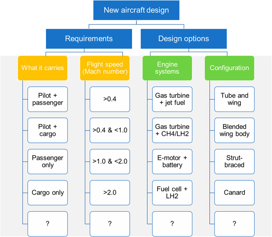
Figure 13. A summary of the domains of possible aircraft designs.
According to the design tool review aforementioned, there is currently no design tools capable of doing all the combinations in Figure 13 especially for an open new design.
Conclusion
Via setting four top-level evaluation questions, a comprehensive review study on aircraft design methods and tools have been carried out. According to our review, most aircraft design tools do not include complete analysis disciplines or at least without balanced considerations of varied disciplines. In addition, the fidelity of most tools are not high. In most cases high fidelity methods have been only used to primary components, e.g., very seldom have design tools included high lift or control devices for analysis and many even have no sufficient description of these components.
MDO levels have been discussed in terms of the number of design variables, coverage of significant disciplines, coupling of airframe and engine parameters, and PIDO framework capability. Together with fidelity, disciplines, components, full MDO with appropriate fidelity levels might be key elements for future aircraft design tasks.
As almost all aircraft design tools do not have configurational optimization capability, future aircraft design tools should work on the determination of a configuration instead of only analyzing or optimization a known configuration.
The ultimate goal is to develop an aircraft design tool with human driven capability, i.e., automatic identifying possible technologies as well as design constraints. Under this condition, as indications for future aircraft design tools, we propose the following aspects: from low fidelity trade-off studies to high fidelity full MDO to deal with new approach and new concept to possibly avoid sub or false optimal solutions due to incomplete disciplines or components or insufficient fidelity levels. Of course, the increased complexity requires improved or totally new PIDO framework.
Author Contributions
YlL: Conceptualization, writing–original draft, writing–review and editing, funding acquisition. SZ: Writing–review and editing. JZ: Writing–review and editing. KY: Writing–review and editing. ML: Writing–review and editing. YtL: Writing–review and editing. All authors contributed to the article and approved the submitted version.
Funding
The author(s) declare that financial support was received for the research, authorship, and/or publication of this article. This work was supported by the Fundamental Research Funds for the Central Universities under Grant No. 226-2024-00031.
Conflict of Interest
The authors declare that the research was conducted in the absence of any commercial or financial relationships that could be construed as a potential conflict of interest.
Supplementary Material
The Supplementary Material for this article can be found online at: https://www.frontierspartnerships.org/articles/10.3389/arc.2024.13096/full#supplementary-material
Footnotes
2It has to be noted that we loosely use TRL = 0 or TRL <1, where TRL = 1 refers to “Basic principles observed and reported” [4].
4https://www.empa.ch/documents/56129/103151/SaT_FLULA2_Dokument/62e3c7e1-e395-4975-9eba-fda3adf17962
5https://www.faa.gov/about/office_org/headquarters_offices/apl/research/models/inm_model/inm7_0c/media/INM_7.0_Technical_Manual.pdf
References
1. Flightpath 2050-Europe’s Vision for Aviation. Advisory Council for Aeronautics Research in Europe. Brussels: EUROPEAN COMMISSION (2011).
2. Liu, Y, Elham, A, Horst, P, and Hepperle, M. Exploring Vehicle Level Benefits of Revolutionary Technology Progress Via Aircraft Design and Optimization. Energies (2018) 11(1):166. doi:10.3390/en11010166
3. Krupa, GP. Application of Agile Model-Based Systems Engineering in Aircraft Conceptual Design. Aeronaut J (2019) 123(1268):1561–601. doi:10.1017/aer.2019.53
4. Ciampa, PD, and Nagel, B. AGILE Paradigm: The Next Generation Collaborative MDO for the Development of Aeronautical Systems. Prog Aerosp Sci (2020) 119:100643. doi:10.1016/j.paerosci.2020.100643
5. Gray, JS, Hwang, JT, Martins, JRRA, Moore, KT, and Naylor, BA. OpenMDAO: An Open-Source Framework for Multidisciplinary Design, Analysis, and Optimization. Struct Multidiscip Optim (2019) 59(4):1075–104. doi:10.1007/s00158-019-02211-z
6. Cardenas Melgar, A, Puri, N, Robertson, BE, and Mavris, DN. Creation of a Structural Model to Facilitate an OpenMDAO-Based Lunar Rover Parametric Sizing Tool. In: AIAA SCITECH 2024 Forum; 8-12 January 2024; Orlando, FL (2024). p. 1–14.
7. Greitzer, EM, Bonnefoy, PA, and DelaRosaBlanco, E. N+ 3 Aircraft Concept Designs and Trade Studies. Volume 1 (2010).
8. Mankins, JC. Technology Readiness Levels: A White Paper, Advanced Concepts Office, Office of Space Access and Technology (1995).
9. Mavris, DN, and Pinon, OJ. A Systems Engineering Approach to Aircraft Design. Hoboken: John Wiley & Sons, Ltd (2010).
10. Sederberg, TW, and Parry, SR. Free-Form Deformation of Solid Geometric Models. In: Proc 13th Annu Conf Comput Graph Interact Tech SIGGRAPH 1986. New York, NY, United States: ACM (1986). p. 151–60.
11. Kroo, I, Altus, S, Braun, R, Gage, P, and Sobieski, I. Multidisciplinary Optimization Methods for Aircraft Preliminary Design. In: 5th Symposium on Multidisciplinary Analysis and Optimization; 07 September 1994 - 09 September 1994; Panama City Beach,FL,U.S.A. (1994).
12. Martins, JRRA, and Lambe, AB. Multidisciplinary Design Optimization: A Survey of Architectures. AIAA J (2013) 51(9):2049–75. doi:10.2514/1.J051895
13. Mader, CA, and Martins, JRRA. Stability-Constrained Aerodynamic Shape Optimization of Flying Wings. J Aircr (2013) 50(5):1431–49. doi:10.2514/1.C031956
14. Sobieszczanski-Sobieski, J, Morris, A, van Tooren, MJL, La Rocca, G, and Yao, W. Multidisciplinary Design Optimization Supported by Knowledge Based Engineering. Hoboken: John Wiley & Sons, Ltd (2015).
15. Torenbeek, E. Synthesis of Subsonic Airplane Design: An Introduction to the Preliminary Design, of Subsonic General Aviation and Transport Aircraft, With Emphasis on Layout, Aerodynamic Design, Propulsion, and Performance/Egbert Torenbeek; With a Foreword by H. Witt. Reprinted. Delft: Delft University Press (1982).
17. Howe, D. Aircraft Conceptual Design Synthesis. London: Professional Engineering Publishing (2000).
18. Raymer, D. Aircraft Design: A Conceptual Approach, Fifth Edition. Reston: American Institute of Aeronautics and Astronautics (2012).
21. Gudmundsson, S. General Aviation Aircraft Design: Applied Methods and Procedures/Snorri Gudmundsson. Oxford: Butterworth-Heinemann (2013).
22. Rentema, DWE. AIDA. Artificial Intelligence Supported Conceptual Design of Aircraft. Delft: Delft University of Technology (2004).
23. Briggs, HC. A Survey of Integrated Tools for Air Vehicle Design, Part I. In: 56th AIAA/ASCE/AHS/ASC Structures, Structural Dynamics, and Materials Conference; 5-9 January 2015; Kissimmee, Florida (2015).
24. Briggs, HC. A Survey of Integrated Tools for Air Vehicle Design, Part II. In: 56th AIAA/ASCE/AHS/ASC Structures, Structural Dynamics, and Materials Conference; 5-9 January 2015; Kissimmee, Florida (2015).
25. Kalogerakis, E, Chaudhuri, S, Koller, D, and Koltun, V. A Probabilistic Model for Component-Based Shape Synthesis. ACM Trans Graph (2012) 31(4):1–11. doi:10.1145/2185520.2185551
26. Haimes, R, and Drela, M. On the Construction of Aircraft Conceptual Geometry for High-Fidelity Analysis and Design. In: 50th AIAA Aerospace Sciences Meeting Including the New Horizons Forum and Aerospace Exposition; 09 January 2012 - 12 January 2012; Nashville, Tennessee (2012).
27. Hwang, JT, Kenway, GKW, and Martins, JRRA. Geometry and Structural Modeling for High-Fidelity Aircraft Conceptual Design Optimization. In: 15th AIAA/ISSMO Multidisciplinary Analysis and Optimization Conference; 16-20 June 2014; Atlanta, GA (2014).
28. Rizzi, A, Zhang, M, Nagel, B, Boehnke, D, and Saquet, P. Towards a Unified Framework Using CPACS for Geometry Management in Aircraft Design. In: 50th AIAA Aerospace Sciences Meeting Including the New Horizons Forum and Aerospace Exposition; 09 January 2012 - 12 January 2012; Nashville, Tennessee (2012).
29. Antoine, N, Kroo, I, Willcox, K, and Barter, G. A Framework for Aircraft Conceptual Design and Environmental Performance Studies. In: 10th AIAA/ISSMO Multidisciplinary Analysis and Optimization Conference; 30 August 2004 - 01 September 2004; Albany, New York (2004).
30. Liersch, CM, and Hepperle, M. A Distributed Toolbox for Multidisciplinary Preliminary Aircraft Design. CEAS Aeronaut J (2011) 2(1):57–68. doi:10.1007/s13272-011-0024-6
31. Drela, M. Simultaneous Optimization of the Airframe, Powerplant, and Operation of Transport Aircraft. In: 2nd Aircraft Structural Design Conference; 26-28 October 2010 (2010).
32. Nickol, C. Conceptual Design Shop. In: Presentation to conceptual aircraft design working group (CADWG21) (2004).
33. Price, M, Raghunathan, S, and Curran, R. An Integrated Systems Engineering Approach to Aircraft Design. Prog Aerosp Sci (2006) 42(4):331–76. doi:10.1016/j.paerosci.2006.11.002
34. Williams, JE, and Vukelich, SR. The USAF Stability and Control Digital DATCOM. Volume I. Users Manual (1979).
35. Drela, M. XFOIL: An Analysis and Design System for Low Reynolds Number Airfoils. In: TJ Mueller, editor. Low Reynolds Number Aerodynamics. Berlin: Springer Berlin Heidelberg (1989).
36. Magnus, AE, and Epton, MA. PAN AIR: A Computer Program for Predicting Subsonic or Supersonic Linear Potential Flows About Arbitrary Configurations Using a Higher Order Panel Method. Volume 1: Theory Document (Version 1.1). Washington, DC: NASA (1981).
37. Drela, M, and Youngren, H. AVL (2006). Available from: http://web.mit.edu/drela/Public/web/avl/ (Accessed 2006).
38. Melin, T. Tornado a Vortex-Lattice MATLAB Implementation for Linear Aerodynamic Wing Applications (2010).
39. Horstmann, KH. Ein Mehrfach-Traglinienverfahren Und Seine Verwendung Fuer Entwurf Und Nachrechnung Nichtplanarer Fluegelanordnungen. Koln: DFVLR (1987).
40. Gur, O, Bhatia, M, Mason, WH, Schetz, JA, Kapania, RK, and Nam, T. Development of a Framework for Truss-Braced Wing Conceptual MDO. Struct Multidiscip Optim (2011) 44(2):277–98. doi:10.1007/s00158-010-0612-9
41. Tomac, M, and Eller, D. From Geometry to CFD Grids—An Automated Approach for Conceptual Design. Prog Aerosp Sci (2011) 47(8):589–96. doi:10.1016/j.paerosci.2011.08.005
43. Dugas, M, and Schroeder, K. FAME-ACSS Documentation (Analytical Calculation of Secondary Wing Structure): Airbus Deutschland GmbH (2004).
44. Cavagna, L, Ricci, S, and Travaglini, L. NeoCASS: An Integrated Tool for Structural Sizing, Aeroelastic Analysis, and MDO at Conceptual Design Level. Prog Aerosp Sci (2011) 47(8):621–35. doi:10.1016/j.paerosci.2011.08.006
45. Wakayama, S, and Kroo, I. The Challenge and Promise of Blended-Wing-Body Optimization. In: 7th AIAA/USAF/NASA/ISSMO Symposium on Multidisciplinary Analysis and Optimization; 02 September 1998 - 04 September 1998; St. Louis,MO,U.S.A. (1998).
46. Andrews, SA, Perez, RE, and Wowk, D. Wing Weight Model for Conceptual Design of Nonplanar Configurations. Aerosp Sci Technol (2015) 43:51–62. doi:10.1016/j.ast.2015.02.011
47. Rizzi, A. Modeling and Simulating Aircraft Stability and Control—The SimSAC Project. Prog Aerosp Sci (2011) 47(8):573–88. doi:10.1016/j.paerosci.2011.08.004
48. Da Ronch, A, Ghoreyshi, M, and Badcock, KJ. On the Generation of Flight Dynamics Aerodynamic Tables by Computational Fluid Dynamics. Prog Aerosp Sci (2011) 47(8):597–620. doi:10.1016/j.paerosci.2011.09.001
49. Chudoba, B, Coleman, G, Smith, H, and Cook, MV. Generic Stability and Control for Aerospace Flight Vehicle Conceptual Design. Aeronaut J (2008) 112(1132):293–306. doi:10.1017/s000192400000227x
50. Mattingly, JD, Heiser, WH, Boyer, KM, Haven, BA, and Pratt, DT. Aircraft Engine Design, Third Edition. Reston: American Institute of Aeronautics and Astronautics (2018). doi:10.2514/4.105173
51. Filippone, A. Advanced Aircraft Flight Performance: Including Environmental Performance, Second Edition. Reston: American Institute of Aeronautics and Astronautics (2022). doi:10.2514/4.106408
52. Hendricks, ES, and Gray, JS. pyCycle: A Tool for Efficient Optimization of Gas Turbine Engine Cycles. Aerospace (2019) 6(8):87. doi:10.3390/aerospace6080087
53. Visser, WPJ, Pieters, H, and Della, CB. Experience With GSP as a Gas Path Analysis Tool. New York: American Society of Mechanical Engineers (2006).
54. Visser, WPJ. Generic Analysis Methods for Gas Turbine Engine Performance: The Development of the Gas Turbine Simulation Program GSP (2015).
56. Kurzke, J, and Halliwell, I Propulsion and Power. Cham: Springer International Publishing (2018). doi:10.1007/978-3-319-75979-1
57. Turner, M. Lessons Learned From the GE90 3-D Full Engine Simulations. In: 48th AIAA Aerospace Sciences Meeting Including the New Horizons Forum and Aerospace Exposition; 04 January 2010 - 07 January 2010; Orlando, Florida (2010).
58. Yang, C, Wu, H, Du, J, Zhang, H, and Yang, J. Full-Engine Simulation of Micro Gas Turbine Based on Time-Marching Throughflow Method. Appl Therm Eng (2022) 217:119213. doi:10.1016/j.applthermaleng.2022.119213
59. Romagnosi, L, Li, Y, Mezine, M, Teixeira, M, Vilmin, S, Anker, JE, et al. A Methodology for Steady and Unsteady Full-Engine Simulations. In: Volume 2C: Turbomachinery; June 17–21, 2019; Phoenix, Arizona, USA (2019).
60. Sarojini, D, Ruh, M, Yan, J, Scotzniovsky, L, Orndorff, NC, Xiang, R, et al. Review of Computational Models for Large-Scale MDAO of Urban Air Mobility Concepts. In: AIAA SCITECH 2024 Forum; 8-12 January 2024; Orlando, FL (2024).
61. El-Refaie, A, and Osama, M. High Specific Power Electrical Machines: A System Perspective. CES Trans Electr Mach Syst (2019) 3(1):88–93. doi:10.30941/CESTEMS.2019.00012
62. Boules, N. Two-Dimensional Field Analysis of Cylindrical Machines With Permanent Magnet Excitation. IEEE Trans Ind Appl (1984) 20(5):1267–77. doi:10.1109/TIA.1984.4504593
63. Zhu, ZQ, and Howe, D. Instantaneous Magnetic Field Distribution in Brushless Permanent Magnet DC Motors. II. Armature-Reaction Field. IEEE Trans Magn (1993) 29(1):136–42. doi:10.1109/20.195558
64. Derbas, HW, Williams, JM, Koenig, AC, and Pekarek, SD. A Comparison of Nodal- and Mesh-Based Magnetic Equivalent Circuit Models. IEEE Trans Energ Convers (2009) 24(2):388–96. doi:10.1109/TEC.2008.2002037
65. Hsieh, M, and Hsu, Y. A Generalized Magnetic Circuit Modeling Approach for Design of Surface Permanent-Magnet Machines. IEEE Trans Ind Electron (2012) 59(2):779–92. doi:10.1109/TIE.2011.2161251
66. Hemeida, A, and Sergeant, P. Analytical Modeling of Surface PMSM Using a Combined Solution of Maxwell–s Equations and Magnetic Equivalent Circuit. IEEE Trans Magn (2014) 50(12):1–13. doi:10.1109/TMAG.2014.2330801
67. Li, Z, Huang, X, Chen, Z, Shi, T, and Yan, Y. Nonlinear Analytical Analysis of External Rotor Permanent Magnet Synchronous Motor. IEEE Trans Magn (2021) 57(6):1–4. doi:10.1109/TMAG.2021.3066687
68. Cao, Z, Huang, Y, Guo, B, Peng, F, Dong, JN, and Hemeida, A. A Novel Hybrid Analytical Model of Active Magnetic Bearing Considering Rotor Eccentricity and Local Saturation Effect. IEEE Trans Ind Electron (2022) 69(7):7151–60. doi:10.1109/TIE.2021.3102396
69. Wu, T, Chen, H, Wang, Q, and Sun, J. Comparison Analysis on the Thermal Runaway of Lithium-Ion Battery Under Two Heating Modes. J Hazard Mater (2018) 344:733–41. doi:10.1016/j.jhazmat.2017.11.022
70. Cericola, D, Ruch, PW, Kötz, R, Novák, P, and Wokaun, A. Simulation of a Supercapacitor/Li-Ion Battery Hybrid for Pulsed Applications. J Power Sourc (2010) 195(9):2731–6. doi:10.1016/j.jpowsour.2009.10.104
71. Cen, J, Li, Z, and Jiang, F. Experimental Investigation on Using the Electric Vehicle Air Conditioning System for Lithium-Ion Battery thermal Management. Energy Sustain Dev (2018) 45:88–95. doi:10.1016/j.esd.2018.05.005
72. Stückl, S, van Toor, J, and Lobentanzer, H. Voltair - the All Electric Propulsion Concept Platform - a Vision for Atmospheric Friendly Flight. In: 28th Congress of the International Council of the Aeronautical Sciences 2012, ICAS 2012 (2012).
73. Cai, H, Xu, C, Liao, Y, Su, L, and Weng, Z. Mass Maldistribution Research of Different Internal Flowing Channels in the Cooling Plate Applied to Electric Vehicle Batteries. Appl Sci (2019) 9(4):636. doi:10.3390/app9040636
74. Poles, D. Base of Aircraft Data (BADA) Aircraft Performance Modelling Report. EEC Technical/Scientific Report 9 (2009).
75. ESDU. Aircraft Performance Program. Part 1: Introduction to the Computer Programs for Aircraft Performance Evaluation (2006).
76. Filippone, A. Comprehensive Analysis of Transport Aircraft Flight Performance. Prog Aerosp Sci (2008) 44(3):192–236. doi:10.1016/j.paerosci.2007.10.005
77. Anemaat, WAJ, Po, K, and Kaushik, B. Aircraft Performance Prediction: Comparison of Classical Handbook Methods to Detailed Time Integration Computer-Aided Methods. SAE Int J Aerosp (2009) 1(1):630–5. doi:10.4271/2008-01-2253
79. Visser, WPJ, Kogenhop, O, and Oostveen, M. A Generic Approach for Gas Turbine Adaptive Modeling. J Eng Gas Turbines Power (2006) 128:13–9. doi:10.1115/1.1995770
81. Anton, E, Lammering, T, and Henke, R. A Comparative Analysis of Operations Towards Fuel Efficiency in Civil Aviation. In: RAeS Applied Aerodynamics Conference: Capabilities and Future Requirements; 27 Wednesday 28 July 2010. Bristol: University of Bristol (2010).
82. Filippone, A. Aircraft Noise Prediction. Prog Aerosp Sci (2014) 68:27–63. doi:10.1016/j.paerosci.2014.02.001
83. Zhang, X, Gill, J, and Angland, D. Aircraft Noise Modeling. In: Encyclopedia of Aerospace Engineering. Hoboken: John Wiley & Sons, Ltd (2010).
84. Koenig, R, Heider, J, and Maierhofer, M. Aircraft Flight Procedure Design With Respect to Noise Abatement as Well as Economical and Pilot Workload Aspects. In: Inter-noise Congress and Exposition on Noise Control Engineering 2005; 07-10 August 2005; Rio de Janeiro, Brazil (2005).
85. Gillian, RE. Aircraft Noise Prediction Program User’s Manual: NASA-TM-84486, L-15064, NAS 1.15:84486. Hampton, VA: NASA Langley Research Center (1982).
86. Sahai, AK. Consideration of Aircraft Noise Annoyance During Conceptual Aircraft Design. Aachen: RWTH Aachen University (2016).
87. Bertsch, L, Dobrzynski, W, and Guérin, S. Tool Development for Low-Noise Aircraft Design. J Aircr (2010) 47(2):694–9. doi:10.2514/1.43188
88. Dahl, MD. Overview of Aircraft Noise Prediction Tools Assessment: NASA Supersonic and Subsonic Fixed Wing Technical Working Group Meeting (2008). Available from: https://ntrs.nasa.gov/citations/20080008146 (Accessed 2008).
89. Dallara, ES, Kroo, IM, and Waitz, IA. Metric for Comparing Lifetime Average Climate Impact of Aircraft. AIAA J (2011) 49(8):1600–13. doi:10.2514/1.j050763
90. Schwartz, E, and Kroo, I. Aircraft Design: Trading Cost and Climate Impact. In: 47th AIAA Aerospace Sciences Meeting Including The New Horizons Forum and Aerospace Exposition; 05 January 2009 - 08 January 2009; Orlando, Florida (2009).
91. MacDonald, T, Clarke, M, Botero, EM, Vegh, JM, and Alonso, JJ. SUAVE: An Open-Source Environment Enabling Multi-Fidelity Vehicle Optimization. In: 18th AIAA/ISSMO Multidisciplinary Analysis and Optimization Conference; 5-9 June 2017; Denver, Colorado (2017).
92. Lammering, T. Integration of Aircraft Systems Into Conceptual Design Synthesis. Aachen: Institute of Aerospace Systems (2014).
93. Liscouët-Hanke, S, Maré, JC, and Pufe, S. Simulation Framework for Aircraft Power System Architecting. J Aircr (2009) 46(4):1375–80. doi:10.2514/1.41304
94. Koeppen, C. Methodik zur modellbasierten Prognose von Flugzeugsystemparametern im Vorentwurf von Verkehrsflugzeugen. Düren: Shaker (2006).
95. Franz, K, Lammering, T, Risse, K, Anton, E, and Hoernschemeyer, R. Economics of Laminar Aircraft Considering Off-Design Performance. In: 8th AIAA Multidisciplinary Design Optimization Specialist Conference; 23 April 2012 - 26 April 2012; Honolulu, Hawaii (2012).
96. Beltramo, MN, Trapp, DL, Kimoto, BW, and Marsh, DP. Parametric Study of Transport Aircraft Systems Cost and Weight: NASA-CR-151970 (1977).
97. Thokala, P, Scanlan, J, and Chipperfield, A. Life Cycle Cost Modelling as an Aircraft Design Support Tool. Proc Inst Mech Eng G J Aerosp Eng (2009) 224(4):477–88. doi:10.1243/09544100jaero574
98. Böhnke, D, Rizzi, A, Zhang, M, and Nagel, B. Towards a Collaborative and Integrated Set of Open Tools for Aircraft Design. In: 51st AIAA Aerospace Sciences Meeting Including the New Horizons Forum and Aerospace Exposition; 07 January 2013 - 10 January 2013; Grapevine (Dallas/Ft. Worth Region), Texas (2013).
99. Wakayama, S. Blended-Wing-Body Optimization Problem Setup. In: 8th Symposium on Multidisciplinary Analysis and Optimization; 06 September 2000 - 08 September 2000; Long Beach,CA,U.S.A. (2000).
100. Anemaat, WAJ. Conceptual Airplane Design Systems. In: Encyclopedia of Aerospace Engineering. Hoboken: John Wiley & Sons, Ltd (2010).
101. Jayaram, S, Myklebust, A, and Gelhausen, P. ACSYNT - A Standards-Based System for Parametric, Computer Aided Conceptual Design of Aircraft. In: Aerospace Design Conference; 03 February 1992 - 06 February 1992; Reston, Virigina (1992).
102. Fredericks, W, Antcliff, K, Costa, G, Deshpande, N, Moore, M, San Miguel, E, et al. Aircraft Conceptual Design Using Vehicle Sketch Pad. In: 48th AIAA Aerospace Sciences Meeting Including the New Horizons Forum and Aerospace Exposition; 04 January 2010 - 07 January 2010; Orlando, Florida (2010).
103. Mccullers, LA. Aircraft Configuration Optimization Including Optimized Flight Profiles. Hampton, VA: NASA. Langley Research Center Recent Experiences in Multidisciplinary Analysis and Optimization, Part 1 (1984).
104. Bradley, KR. A Sizing Methodology for the Conceptual Design of Blended-Wing-Body Transports (2004).
106. Lytle, JK. The Numerical Propulsion System Simulation: An Overview. In: Computational Aerosciences; 15-17 February 2000; California (2000).
107. Hahn, A. Vehicle Sketch Pad: A Parametric Geometry Modeler for Conceptual Aircraft Design. In: 48th AIAA Aerospace Sciences Meeting Including the New Horizons Forum and Aerospace Exposition; 04 January 2010 - 07 January 2010; Orlando, Florida (2010).
109. Kroo, I “A Quasi-Procedural, Knowledge-Based System for Aircraft Design,” in Aircraft Design, Systems and Operations Conference, AIAA 1988-4428 (2017). Available from: https://arc.aiaa.org/doi/10.2514/6.1988-4428 (Accessed 1998).
110. Kroo, I. An Interactive System for Aircraft Design and Optimization. In: Aerospace Design Conference; 03 February 1992 - 06 February 1992; Reston, Virigina (1992).
111. Allison, J, Roth, B, Kokkolaras, M, Kroo, I, and Papalambros, P. Aircraft Family Design Using Decomposition-Based Methods. In: 11th AIAA/ISSMO Multidisciplinary Analysis and Optimization Conference; 06 September 2006 - 08 September 2006; Portsmouth, Virginia (2006).
112. Antoine, NE, and Kroo, IM. Aircraft Optimization for Minimal Environmental Impact. J Aircr (2012) 41(4):790–7. doi:10.2514/1.71
113. Schwartz, E, and Kroo, I. Aircraft Design for Reduced Climate Impact. In: 49th AIAA Aerospace Sciences Meeting Including the New Horizons Forum and Aerospace Exposition; 04 January 2011 - 07 January 2011; Orlando, Florida (2011).
114. Xu, J, and Kroo, I. Aircraft Design With Active Load Alleviation and Natural Laminar Flow. J Aircr (2014) 51(5):1532–45. doi:10.2514/1.c032402
115. Antoine, NE. Aircraft Optimization for Minimal Environmental Impact. Stanford: Stanford University (2004).
116. Durston, DA. LinAir: A Multi-Element Discrete Vortex Weissinger Aerodynamic Prediction Method (1993).
117. Botero, EM, Wendorff, A, MacDonald, T, Variyar, A, Vegh, JM, Lukaczyk, TW, et al. SUAVE: An Open-Source Environment for Conceptual Vehicle Design and Optimization. In: 54th AIAA Aerospace Sciences Meeting; 4-8 January 2016; San Diego, California, USA (2016).
118. MacDonald, T, Botero, E, Vegh, JM, Variyar, A, Alonso, JJ, Orra, TH, et al. SUAVE: An Open-Source Environment Enabling Unconventional Vehicle Designs Through Higher Fidelity. In: 55th AIAA Aerospace Sciences Meeting; 9 - 13 January 2017; Grapevine, Texas (2017).
119. Perez, RE, Jansen, PW, and Martins, JRRA. pyOpt: A Python-Based Object-Oriented Framework for Nonlinear Constrained Optimization. Struct Multidiscip Optim (2012) 45(1):101–18. doi:10.1007/s00158-011-0666-3
120. Greitzer, EM, Bonnefoy, PA, and la Rosa Blanco, E. N+ 3 Aircraft Concept Designs and Trade Studies. Volume 2: Appendices-Design Methodologies for Aerodynamics, Structures, Weight, and Thermodynamic Cycles (2010).
122. Boyd, S, Kim, SJ, Vandenberghe, L, and Hassibi, A. A Tutorial on Geometric Programming. Optim Eng (2007) 8(1):67–127. doi:10.1007/s11081-007-9001-7
123. Hoburg, W, and Abbeel, P. Geometric Programming for Aircraft Design Optimization. AIAA J (2014) 52(11):2414–26. doi:10.2514/1.j052732
124. Kirschen, GP. Signomial Programming for Aircraft Design. Cambridge: Massachusetts Institute of Technology (2016).
125. Kirschen, PG, York, MA, Ozturk, B, and Hoburg, WW. Application of Signomial Programming to Aircraft Design. J Aircr (2017) 54(1):1–23.
126. York, MA, Hoburg, WW, and Drela, M Turbofan Engine Sizing and Tradeoff Analysis Via Signomial Programming. J Aircr (2017).
127. Werner-Westphal, C, Heinze, W, and Horst, P. Multidisciplinary Integrated Preliminary Design Applied to Unconventional Aircraft Configurations. J Aircr (2008) 45(2):581–90. doi:10.2514/1.32138
128. Werner-Spatz, C, Heinze, W, and Horst, P. Improved Representation of High-Lift Devices for a Multidisciplinary Conceptual Aircraft Design Process. J Aircr (2009) 46(6):1984–94. doi:10.2514/1.42845
129. Hansen, LU, Heinze, W, and Horst, P. Blended Wing Body Structures in Multidisciplinary Pre-Design. Struct Multidiscip Optim (2008) 36(1):93–106. doi:10.1007/s00158-007-0161-z
130. Radespiel, R, and Heinze, W. SFB 880: Fundamentals of High Lift for Future Commercial Aircraft. CEAS Aeronaut J (2014) 5(3):239–51. doi:10.1007/s13272-014-0103-6
131. Werner-Spatz, C, Heinze, W, Horst, P, and Radespiel, R. Multidisciplinary Conceptual Design for Aircraft With Circulation Control High-Lift Systems. CEAS Aeronaut J (2012) 3(2-4):145–64. doi:10.1007/s13272-012-0049-5
132. Krosche, M, and Heinze, W. Robustness Analysis of an Aircraft Design for Short Takeoff and Landing. J Aircr (2015) 52(4):1235–46. doi:10.2514/1.c032876
133. Hoelzen, J, Liu, Y, Bensmann, B, Winnefeld, C, Elham, A, Friedrichs, J, et al. Conceptual Design of Operation Strategies for Hybrid Electric Aircraft. Energies (2018) 11(1):217. doi:10.3390/en11010217
134. Risse, K, Lammering, T, Anton, E, Franz, K, and Hoernschemeyer, R. An Integrated Environment for Preliminary Aircraft Design and Optimization. In: 8th AIAA Multidisciplinary Design Optimization Specialist Conference; 23 April 2012 - 26 April 2012; Honolulu, Hawaii (2012).
135. Lammering, T, Anton, E, Risse, K, Franz, K, and Hoernschemeyer, R. Influence of Offdesign Performance on Design Synthesis of Laminar Aircraft. J Aircr (2012) 49(5):1324–35. doi:10.2514/1.c031663
136. Risse, K, Schäfer, K, Schültke, F, and Stumpf, E. Central Reference Aircraft Data System (CeRAS) for Research Community. CEAS Aeronaut J (2016) 7(1):121–33. doi:10.1007/s13272-015-0177-9
137. Lammering, T, Anton, E, and Henke, R. Validation of a Method for Fast Estimation of Transonic Aircraft Polars and Its Application in Preliminary Design. In: RAeS Applied Aerodynamics Conference: Capabilities and Future Requirements; 27 - Wednesday 28 July 2010. Bristol: University of Bristol (2010).
138. Franz, K, Risse, K, and Stumpf, E. Framework for Sustainability-Driven Aircraft Design. In: 2013 Aviation Technology, Integration, and Operations Conference; August 12-14, 2013; Los Angeles, CA (2013).
139. Amadori, K. On Aircraft Conceptual Design: A Framework for Knowledge Based Engineering and Design Optimization. Thesis. Institutionen för ekonomisk och industriell utveckling (2008). Available from: http://liu.diva-portal.org/smash/get/diva2:18279/FULLTEXT01.pdf (Accessed 2008).
140. Safavi, E. Collaborative Multidisciplinary Design Optimization for Conceptual Design of Complex Products: Linköping Studies in Science and Technology. Dissertations. Linkoping: Linköping University Electronic Press (2016).
141. Munjulury, RC. Knowledge-Based Integrated Aircraft Design: An Applied Approach From Design to Concept Demonstration: Linköping Studies in Science and Technology. Dissertations. Linkoping: Linköping University Electronic Press (2017).
142. Rizzi, A, Eliasson, P, Goetzendorf-Grabowski, T, Vos, JB, Zhang, M, and Richardson, TS. Design of a Canard Configured TransCruiser Using CEASIOM. Prog Aerosp Sci (2011) 47(8):695–705. doi:10.1016/j.paerosci.2011.08.011
143. Richardson, TS, Beaverstock, C, Isikveren, A, Meheri, A, Badcock, K, and Da Ronch, A. Analysis of the Boeing 747-100 Using CEASIOM. Prog Aerosp Sci (2011) 47(8):660–73. doi:10.1016/j.paerosci.2011.08.009
144. Zhang, M. Contributions to Variable Fidelity MDO Framework for Collaborative and Integrated Aircraft Design. Stockholm: KTH Royal Institute of Technology (2015).
145. Jungo, A, Zhang, M, Vos, JB, and Rizzi, A. Benchmarking New CEASIOM With CPACS Adoption for Aerodynamic Analysis and Flight Simulation. Aircr Eng Aerosp Technol (2018) 90(4):613–26. doi:10.1108/AEAT-11-2016-0204
146. La Rocca, G, and Van Tooren, MJ. Knowledge-Based Engineering Approach to Support Aircraft Multidisciplinary Design and Optimization. J Aircr (2009) 46(6):1875–85. doi:10.2514/1.39028
147. Elmendorp, RJM, Vos, R, and La Rocca, G. A Conceptual Design and Analysis Method for Conventional and Unconventional Airplanes. In: 29th Congress of the International Council of the Aeronautical Sciences; 7-12 September 2014; St. Petersburg, Russia. International Council of Aeronautical Sciences (2014).
148. Brown, M, and Vos, R. Conceptual Design and Evaluation of Blended-Wing Body Aircraft. In: 2018 AIAA Aerospace Sciences Meeting; 8–12 January 2018; Kissimmee, Florida (2018).
149. Feagin, RC, and Morrison, WD. Delta Method, an Empirical Drag Buildup Technique. NASA-CR-151971 (1978).
150. Elham, A, La Rocca, G, and Van Tooren, MJL. Development and Implementation of an Advanced, Design-Sensitive Method for Wing Weight Estimation. Aerosp Sci Technol (2013) 29(1):100–13. doi:10.1016/j.ast.2013.01.012
151. Perez, R, and Martins, J. pyACDT: An Object-Oriented Framework for Aircraft Design Modelling and Multidisciplinary Optimization. In: 12th AIAA/ISSMO Multidisciplinary Analysis and Optimization Conference; 10 September 2008 - 12 September 2008; Victoria, British Columbia, Canada (2008).
152. Henderson, RP, Martins, JRRA, and Perez, RE. Aircraft Conceptual Design for Optimal Environmental Performance. Aeronaut J (2012) 116(1175):1–22. doi:10.1017/s000192400000659x
153. Trifari, V, Ruocco, M, Cusati, V, Nicolosi, F, and De Marco, A. Java Framework for Parametric Aircraft Design – Ground Performance. Aircr Eng Aerosp Technol (2017) 89(4):599–608. doi:10.1108/aeat-11-2016-0209
154. Nicolosi, F, De Marco, A, Attanasio, L, and Della Vecchia, P. Development of a Java-Based Framework for Aircraft Preliminary Design and Optimization. J Aerosp Inf Syst (2016) 13(6):234–42. doi:10.2514/1.i010404
155. Böhnke, D. A Multi-Fidelity Workflow to Derive Physics-Based Conceptual Design Methods. DLR German Aerospace Center (2015).
156. Bohari, B, Borlon, Q, Mendoza-Santos, PB, Sgueglia, A, Benard, E, Bronz, M, et al. Conceptual Design of Distributed Propellers Aircraft: Non-Linear Aerodynamic Model Verification of Propeller-Wing Interaction in High-Lifting Configuration. In: 2018 AIAA Aerospace Sciences Meeting; 8–12 January 2018; Kissimmee, Florida (2018).
157. Tai, J. System Assessment of Novel Aircraft Concepts: Collaborative Research Center 880: Fundamentals of High Lift for Future Civil Aircraft - New Engine Integration Concepts Symposium (2021).
158. Salas, NL, Tai, JC, and Mavris, DN. The Environmental Design Space: Modeling and Performance Updates. In: AIAA Scitech 2021 Forum; 11–15 and 19–21 January 2021 (2021).
159. Corman, JA, Weston, N, Friedland, C, Mavris, DN, and Laughlin, TW. Rapid Airframe Design Environment (RADE): A Parametric, Modular, and Multidisciplinary Framework for Conceptual Phase Airframe Design. In: 2018 AIAA Modeling and Simulation Technologies Conference; 8–12 January 2018; Kissimmee, Florida (2018).
160. Giesing, J, and Barthelemy, JF. A Summary of Industry MDO Applications and Needs. In: 7th AIAA/USAF/NASA/ISSMO Symposium on Multidisciplinary Analysis and Optimization; 02 September 1998 - 04 September 1998; St. Louis,MO,U.S.A. (1998).
161. Munjulury, RC, Staack, I, Berry, P, and Krus, P. A Knowledge-Based Integrated Aircraft Conceptual Design Framework. CEAS Aeronaut J (2016) 7(1):95–105. doi:10.1007/s13272-015-0174-z
162. Hwang, J, and Martins, J. GeoMACH: Geometry-Centric MDAO of Aircraft Configurations With High Fidelity. In: 12th AIAA Aviation Technology, Integration, and Operations (ATIO) Conference and 14th AIAA/ISSMO Multidisciplinary Analysis and Optimization Conference; 17 September 2012 - 19 September 2012; Indianapolis, Indiana (2012).
163. Heath, C, and Gray, J. OpenMDAO: Framework for Flexible Multidisciplinary Design, Analysis and Optimization Methods. In: 53rd AIAA/ASME/ASCE/AHS/ASC Structures, Structural Dynamics and Materials Conference (2012).
164. Riggins, B, Locatelli, D, Schetz, J, Kapania, R, and Poquet, T. Development of a Multi-Disciplinary Optimization Framework for Nonconventional Aircraft Configurations in PACELAB APD. SAE Tech Pap Series (2015). doi:10.4271/2015-01-2564
165. Raymer, D. Conceptual Design Modeling in the RDS-Professional Aircraft Design Software. In: 49th AIAA Aerospace Sciences Meeting Including the New Horizons Forum and Aerospace Exposition; 04 January 2011 - 07 January 2011; Orlando, Florida (2011).
166. Liu, H, Wu, Z, and Raymer, DP. Automated Scheme Adjustment for Conceptual Aircraft Design and Optimization. J Aircr (2006) 43(3):825–31. doi:10.2514/1.14138
167. Lukaczyk, TW, Wendorff, AD, Colonno, M, Economon, TD, Alonso, JJ, Orra, TH, et al. SUAVE: An Open-Source Environment for Multi-Fidelity Conceptual Vehicle Design. In: 16th AIAA/ISSMO Multidisciplinary Analysis and Optimization Conference; 22-26 June 2015; Dallas, TX (2015).
Keywords: aircraft design, multidisciplinary design optimization, knowledge-based engineering, system engineering, modelling and simulation
Citation: Liu Y, Zhang S, Zhang J, Yao K, Luo M and Liu Y (2024) Towards the Design of Future Aircraft: A Critical Review On the Tools and Methodologies. Aerosp. Res. Commun. 2:13096. doi: 10.3389/arc.2024.13096
Received: 06 April 2024; Accepted: 09 May 2024;
Published: 30 May 2024.
Copyright © 2024 Liu, Zhang, Zhang, Yao, Luo and Liu. This is an open-access article distributed under the terms of the Creative Commons Attribution License (CC BY). The use, distribution or reproduction in other forums is permitted, provided the original author(s) and the copyright owner(s) are credited and that the original publication in this journal is cited, in accordance with accepted academic practice. No use, distribution or reproduction is permitted which does not comply with these terms.
*Correspondence: Yaolong Liu, bGl1eWFvbG9uZ0B6anUuZWR1LmNu