Abstract
Supersonic and hypersonic flows have gained considerable attention in the aerospace industry in recent years. Flow control is crucial for refining the quality of these high-speed flows and improving the performance and safety of fast aircraft. This paper discusses the distinctive characteristics of supersonic flows compared to low-speed flows, including phenomena such as boundary layer transition, shock waves, and sonic boom. These traits give rise to significant challenges related to drag, noise, and heat. Therefore, a review of several active and passive control strategies is provided, highlighting their significant advancements in flow transitions, reducing drag, minimizing noise, and managing heat. Furthermore, we provide a comprehensive analysis of various research methodologies used in the application of flow control engineering, including wind tunnel testing, flight testing, and computational fluid dynamics (CFD). This work gives an overview of the present state of flow control research and offers insights into potential future advancements.
Introduction
Since Colonel Yeager piloted the X-1 aircraft to break the sound barrier in 1947 [1], humanity officially entered the supersonic era, as shown in Figure 1. Researchers and engineers have embarked on various scientific explorations and engineering practices in the field of high-speed manned or unmanned aircrafts [2]. The variable Mach number, Ma, is a non-dimensional parameter utilized to quantify compressibility in fluid dynamics, typically employed to differentiate between subsonic (Ma < 1) and supersonic (Ma > 1) flow. In contrast to subsonic flow, the supersonic flow exhibits distinctive physical phenomena, including shock waves, compressibility effects, and boundary layer transition dominated by the second mode, as illustrated in Figure 2. Hsue-Shen Tsien [7] first proposed that when Ma ≥ 5, the flow might be classified as hypersonic flow. Over time, individuals gradually recognized the importance of hypersonic flow, and investigations uncovered several distinct attributes of hypersonic flow in comparison to supersonic flow, such as thin shock layers, entropy layers, viscous interactions, high-temperature flow, low-density flow, real gas effects, and chemical non-equilibrium effects.
FIGURE 1
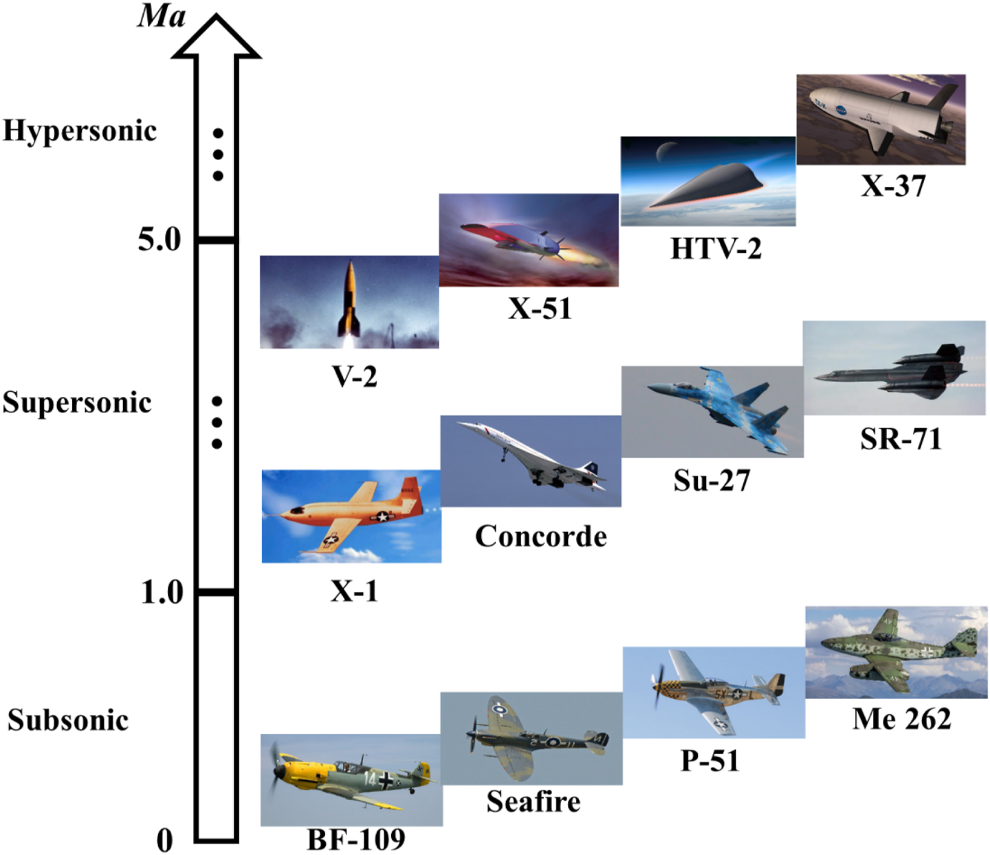
Some famous aircraft and their flight Mach numbers.
FIGURE 2
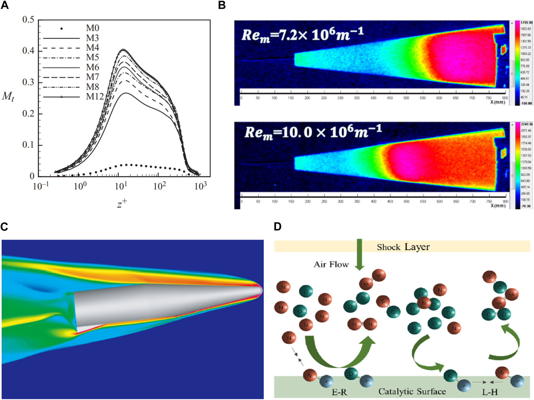
Supersonic and hypersonic aircraft and complex flow phenomena [3–6]. (A) Compressibility effects (B) Boundary layer transition. (C) Shock waves (D) Chemical reaction.
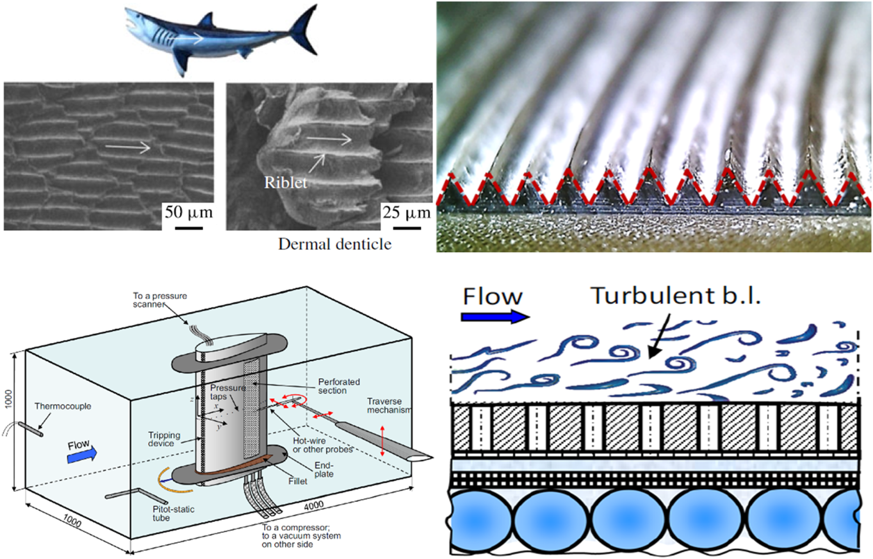
Boundary layers and flow control are closely linked concepts. The idea of flow control has been there since Prandtl first introduced boundary layer theory in the early days. The study of laminar and turbulent flows has historically placed great emphasis on flow control, which has wide-ranging applications in aerospace engineering. The objective of flow control is to enhance the qualities of fluids, such as lift-drag ratio, thermal protection, noise reduction, vibration attenuation, etc. [8–10], by using various methods to modify the flow patterns and evolutionary structures. These methods include altering flow separation, compressible mixing, turbulent transition, and more. In the 1970s, NASA Langley Research Center discovered that the tooth-like structure on the sharks’ surface could decrease flow resistance while fast swimming. As a result, several groove control techniques were developed for aircraft surfaces, as shown in Figure 3. The blowing/suction technique involves adding or subtracting energy into the boundary layer to modify the properties of the average velocity profile. This can lead to a more active boundary layer or a thinner newly formed boundary layer, which aids in modifying the pressure gradient caused by flow separation and associated flow instability. The design of flow control systems is extremely intricate due to the complex interactions between shock waves and boundary layers, as well as the coupling effects of high-temperature, high-pressure, and strong discontinuities in high-speed flows. Despite their effectiveness and widespread use in engineering applications, these techniques also face significant challenges.
This paper presents a comprehensive analysis of flow control strategies and their advancements in the field of supersonic and hypersonic flows. The work focuses on the fundamental attributes of supersonic and hypersonic flows, and highlights the significance of investigating flow control within these regimes. The paper is organized as follows: The initial section introduces the attributes of supersonic and hypersonic flows and examines the significance of investigating flow control in these conditions. The second section presents the research progress in several typical phenomena: boundary layer transition, shock wave trains, shock wave/boundary layer interactions, and sonic boom. The third section shows common flow control strategies, examining them extensively within the frameworks of active control and passive control. The fourth section of the study concentrates on research methodologies for high-speed compressible flows, specifically examining research findings in the area of supersonic and hypersonic flow control. This analysis is conducted through the perspectives of CFD techniques, wind tunnel testing techniques, and flight testing techniques. The review of supersonic and hypersonic flow control techniques provides valuable insights into possible future research avenues.
Typical Phenomena of Supersonic and Hypersonic Flows
Boundary Layer and Flow Transition
A boundary layer transition from laminar to turbulent flow occurs when the Reynolds number exceeds the critical threshold [14], as shown in Figure 4. Accurately predicting flow transition and understanding the underlying flow mechanism are of utmost importance in engineering. Research discovered that the frictional resistance coefficient increases by a factor of 4 times [16] when the supersonic boundary layer with a freestream of Ma = 3 transitions. Following the transition of the hypersonic boundary layer, the turbulent region often experiences a significant increase in both friction resistance and heat flux, often reaching levels that are 3–5 times higher than before [17]. The literatures [18] review the progress of hypersonic boundary layer transition and highlights the limits of the current predominant approaches of predicting transition, which typically rely on transition data or empirical formulas. It also pointed out that flight tests can serve as a viable approach for conducting transition studies in authentic flight situations. Many countries have carried out many transition flight tests, such as the Hypersonic Boundary Layer Transition (HyBOLT) transition control flight test conducted by the United States, and the compression surface transition of the scramjet forebody (LEA) the flight test carried out by France. Aircraft Flight Tests section will introduce these flight tests in detail.
FIGURE 4
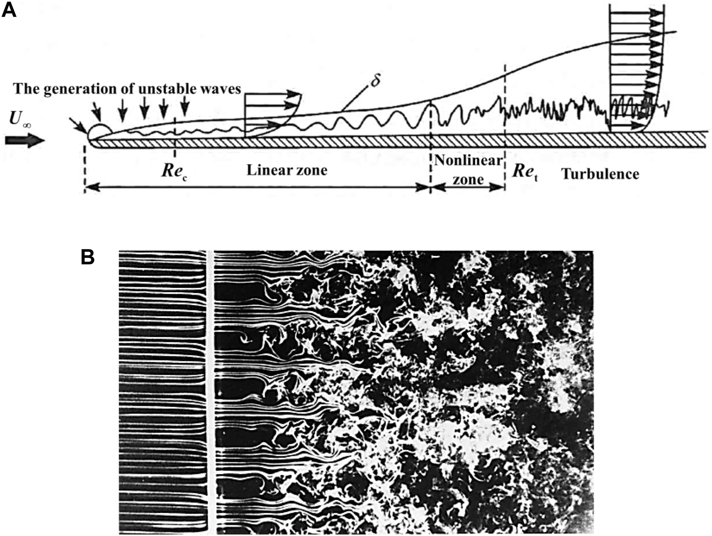
Experimental and schematic diagram of the transition process. (A) Schematic diagram of the transition process [14]. (B) Experimental diagram of the transition process [15].
As a necessary experimental facility for simulating real flight, hypersonic wind tunnels play a pivotal role in the study of boundary layer transition. As shown in Figure 5, the quiet wind tunnel [19] built by the National Laboratory of Turbulence and Complex Systems of Peking University can cover supersonic and hypersonic flows in the range of Ma 3.0∼6.5 with the diameter of nozzle exit being 300 mm. At present, the relatively powerful and easy-to-use near-wall measurement technologies mainly include temperature-sensitive paint (TSP), near-wall particle image velocimetry and Rayleigh-scattering visualization. They provide good experimental measurement methods for research transition. In addition, TSP is a non-contact optical temperature measurement technology that can achieve high spatial resolution temperature field measurement.
FIGURE 5
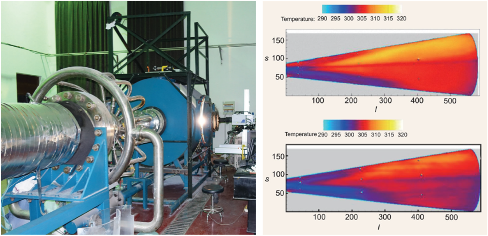
Ma 6.0 low-noise wind tunnel of Peking University [19].
The hypersonic flow, being a type of high-enthalpy motion, must take into account some unique phenomena, including the failure of the calorically perfect gas assumption, thermochemical non-equilibrium effects, molecular vibration energy excitation, molecular ionization, material ablation, etc. Numerical modeling methods for high enthalpy flow transition and turbulence simulation [20] necessitate the development of many techniques, including real gas models and high-enthalpy boundary layer stability models. Several flow control strategies available for managing high enthalpy boundary layers were proposed, including but not limited to: 1) CO2 injection, 2) wall blowing/suction, 3) wall porous coatings, and 4) roughness elements. The effectiveness of flow control in delaying the transition of hypersonic boundary layers in four forms of instability, namely, streamwise traveling waves instability, crossflow instability, Görtler instability, and attachment line instability, was highlighted by Liu et al. [21]. The employed techniques encompassed 1) roughness elements and finite amplitude band control, 2) wavy walls, 3) microporous surfaces, 4) localized heating/cooling of walls, 5) heavy gas injection, 6) synthetic jet, 7) blowing/suction, and so forth. The experimental progress in controlling hypersonic boundary layer transition was reviewed by Yang et al. [22]. The flow control techniques were thoroughly summarized and outlined, including roughness elements, cavities, porous walls, wavy walls, jets, wall cooling/heating, plasma, and more. Special emphasis was placed on the feasibility of plasma control to postpone the transition of hypersonic boundary layer.
To date, researchers have achieved proficiency in employing uncomplicated techniques to forecast the transition of boundary layers across fundamental geometries [23, 24]. Additionally, they have devised related algorithms or software [25], which offer valuable support for contemporary flow control analysis and engineering application [26]. However, the transition of hypersonic boundary layers remains a challenging task, and the underlying flow mechanisms are not yet completely comprehended. The aerodynamic and thermal protection design of the next-generation of hypersonic aircraft largely depends on the depth of understanding of transition mechanisms and the ability to control them.
Shock Wave Trains
A series of shock waves, which are frequently seen in supersonic inlets and at the heads of aircraft, define shock wave train, a complicated flow phenomenon [27]. Shock/shock interaction, which is intricately linked to shock wave trains, is a significant area of interest and obstacle. Understanding the mechanics of the subject matter and providing an accurate description and prognosis had substantial academic and practical significance. Schematic representations depicting six distinct shock/shock interactions on a blunt leading edge are illustrated in Figure 6.
FIGURE 6
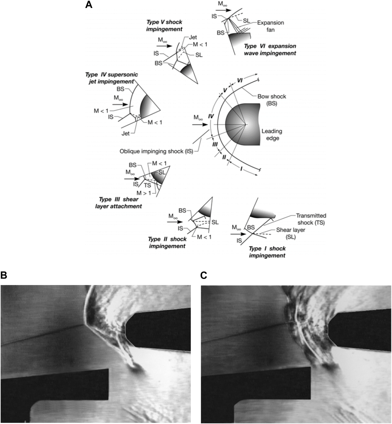
Shock/shock interactions on a cowl leading edge [28]. (A) Six types of shock/shock interaction. (B) Type III before transition. (C) Type III after transition.
A study was conducted to provide a comprehensive understanding of internal structures, oscillatory behaviors, and active/passive controls of shock wave trains [29]. The control methods in this study encompass three main approaches: 1) boundary layer suction, 2) bump control, 3) vortex generator. Via utilizing intelligent sensing technology, real-time information in the flow field is reconstructed. By employing adaptive adjustment of the suction air or vortex generator switch, the working efficiency is enhanced throughout a broad spectrum of inflow conditions. Luo et al. [30] provided detailed information on various techniques for controlling shock waves at the leading edge. These techniques include reverse jet flow, laser energy deposition, and plasma synthetic jets. For controlling oblique shock waves in the inlet and side wings, the main methods include plasma discharge, compression corner control, and magnetohydrodynamic methods. For controlling shock/shock interaction, the main methods include reverse supersonic jets, laser-based energy deposition methods, and plasma discharge.
As shown in Figure 7, in the SAV21 supersonic cascade [27], the shock wave train induced by high back pressure exhibits highly three-dimensional structure, facilitating the passage of the leading edge of the shock wave train down the throat. This phenomenon leads to a decrease in the mass-capturing coefficient and the occurrence of stall. When designed surface or end-wall suction slots were adopted, the maximum back pressure could be improved by 20%. Zhang et al. [31] investigated the asymmetry of oblique shock wave trains at Ma = 2.7. The experimental findings demonstrated that the oblique shock wave trains exhibited flow separation regions upon travelling ramps, characterized by a rapid increase in their motion velocity. Additionally, the direction of asymmetric separation deflection may undergo a change. Based on the interaction characteristics between the oblique shock wave train and upstream shocks, the slope control in the pipeline is employed to generate asymmetric upstream flow conditions by manipulating the deflection direction of the oblique shock wave trains.
FIGURE 7
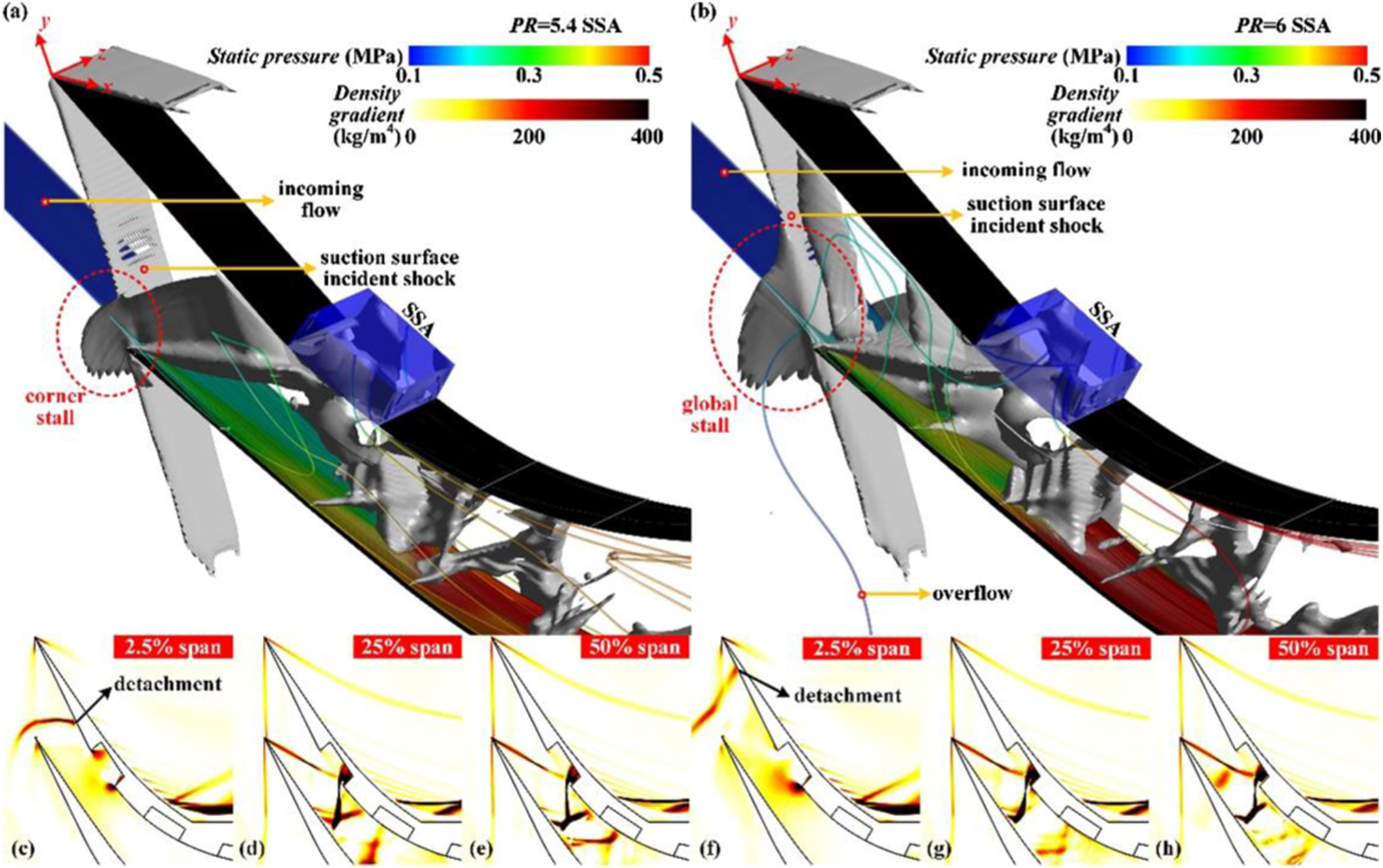
Three-dimensional shock wave train in the SAV21 supersonic cascade [27]. (A) the isosurface of the streamwise density gradient at a contour value of 0.5 × ∂ρ/∂x −0.87 × ∂ρ/∂y = 110) and space streamlines rendered with static pressure contour when backpressure ratio PR = 5.4. (B) the isosurface of the streamwise density gradient at a contour value of 0.5 × ∂ρ/∂x −0.87 × ∂ρ/∂y = 110) and space streamlines rendered with static pressure contour when backpressure ratio PR = 6. (C) streamwise density gradient contour at 2.5% spans when PR = 5.4. (D) streamwise density gradient contour at 25% spans when PR = 5.4. (E) streamwise density gradient contour at 50% spans when PR = 5.4. (F) streamwise density gradient contour at 2.5% spans when PR = 6. (G) streamwise density gradient contour at 25% spans when PR = 6. (H) streamwise density gradient contour at 50% spans when PR = 6.
Shock Waves/Boundary Layer Interactions (SWBLI)
The presence of shock waves/boundary layer interactions is prevalent in the flow patterns both within and outside transonic, supersonic, and hypersonic aircraft. Since first observed by Ferri [32] in 1939, it has quickly become a hot topic in the research of supersonic flow control. Simplified models are proposed to investigate the underlying physical mechanism of shock wave/boundary layer interactions, as shown in Figure 8, owing to the intricate nature. Swept compression ramps are commonly found in the inlets or surfaces of supersonic/hypersonic aircraft. Similarly, the utilization of dual-fin design is frequently observed in the upper sections of sidewall compressions. Surface protrusions on aircraft surfaces are frequently fabricated using cylinders, half cones, and fins as their primary shapes.
FIGURE 8
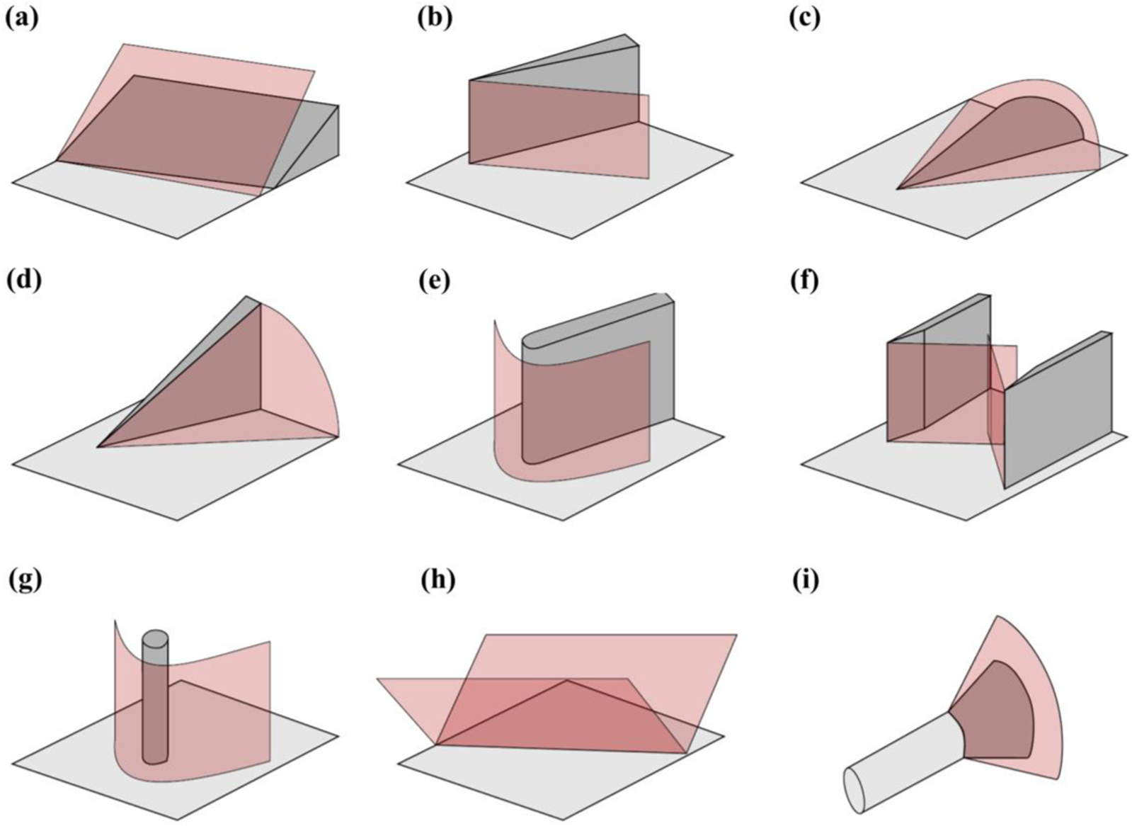
Canonical three-dimensional SWBLI configurations in high-speed aircraft applications [33]. (A) swept compression conrner. (B) sharp unswept fin. (C) semi-cone. (D) swept fin. (E) blunt fin. (F) double fin. (G) vertical cylinder. (H) swept impinging shock. (I) flared cylinder.
What we need to regulate is the most important aspect of flow control. Dolling [34] considered that the flow control of shock wave/boundary layer interactions was to reduce peak heat flux, decrease the fluctuating pressure loads, diminish the scale of separated flow, and move the frequency of fluctuation outside of the critical range. There are three strategies for controlling shock wave/boundary layer interactions summarized [35]: 1) increasing energy in the bottom layer of the boundary layer to enhance its resistance to adverse pressure gradients; 2) reducing pressure differences before and after shock waves in the near-wall region; 3) injecting energy to increase wall temperature, which raises the speed of sound and lowers the intensity of the shock wave. Specifically, methods such as bleeding and transpiration, perforations and porous media, MART technology (Mesoflaps for Aeroelastic Recirculating Transpiration, MART), streamwise slots, secondary flow circulation, and wall bump were employed. Zhong et al. [36] provided an overview of the evolution of shock/boundary layer interactions and its impacts on the flow process. Furthermore, Shi et al. [37] elaborated on methods for controlling shock wave/turbulent boundary layer interactions, including micro-vortex generators, plasma control, electromagnetic coupling effects, and other techniques.
The interaction between shocks and boundary layers is an inherent physical phenomenon that is commonly observed in high-speed aircraft. This phenomenon can manifest in several areas, including inlets, flow corners, and wings. Nevertheless, the majority of existing flow control studies primarily concentrate on supersonic flow characterized by Mach numbers spanning from 1 to 4, and there is still little research on hypersonic flows. Consequently, there is a pressing requirement for further exploration of hypersonic flow in forthcoming research endeavors. Furthermore, it is crucial to consider the significance of low-frequency oscillations [38] in the flow control of shock/boundary layer interactions.
Sonic Boom
The phenomenon of sonic boom is exclusive to supersonic flight. As illustrated in Figure 9, when an aircraft operates at supersonic speeds, its components and the gas emitted will cause significant disruptions in the surrounding air, leading to the formation of shock/expansion wave systems. The interaction and propagation of these wave systems towards the ground result in the formation of two primary shock waves, known as leading and trailing. As these two shock waves sweep across the ground, an observer perceives two explosive-like sounds, which are referred to as a “sonic boom” [40].
FIGURE 9
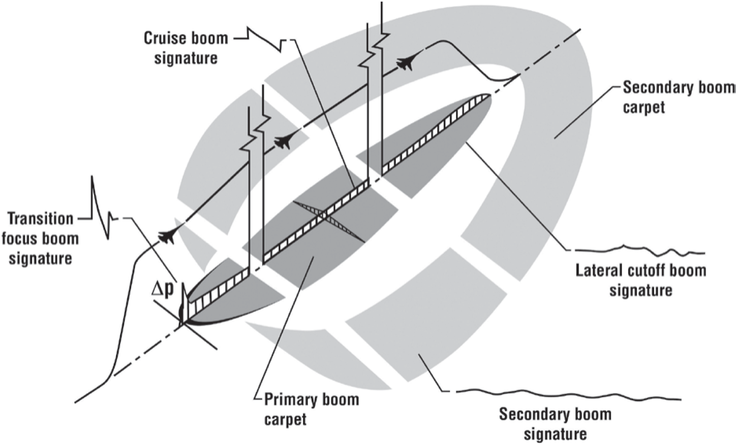
Schematic diagram of sonic boom [39].
Zhang et al. [40] conducted a review on the sonic booms, covering the generation mechanisms, prediction methods and suppression techniques. The flow controls involved in mitigating sonic booms include: 1) quite spike, 2) staged aft body, 3) energy injection, 4) membrane vibration. Sonic boom refers to the acoustic phenomena that occurs when pressure waves originating from a supersonic source propagate through the atmosphere [41], and the flow control will be an important means for suppressing sonic booms in future supersonic civil aircraft. There are several potential flow control systems that could be considered for future application. These tactics encompass thermal energy injection, electromagnetic focusing, acoustic impedance, and vectored thrust engine technology. It was found that the use of a noise-reducing nose cone on an aircraft [42] leads to a notable decrease in the magnitude of the sonic boom, but with a slight increase in the drag coefficient. The critical length of the quiet cone varies with the flying altitude and the Mach number. Therefore, the use of multi-stage quiet cones with each level reaching its critical length was suggested. Ye et al. [43, 44]proposed an active control method of suppressing sonic booms. The proposed technique entails the establishment of an aperture in close proximity to the leading edge of the lower surface of an airfoil to facilitate suction. Simultaneously, an ejecting flow is introduced at the trailing edge of the aforementioned surface, while ensuring an equitable distribution of suction and ejection. The proposed methodology has the potential to substantially reduce the sonic boom level and flow drag experienced by supersonic aircraft. When a mass flow rate of 7.5 kg/s was applied to a NACA0008 airfoil, the absolute value of the maximum negative overpressure decreased by 56.77% and the drag coefficient was reduced by 10.96%.
Flow Control Strategies
Flow control strategies refer to the manipulation of flow characteristics and properties through artificial interventions to meet certain requirements or accomplish specified goals. They can be categorized into two groups based on whether the energy input is active or passive. Passive controls encompass several strategies such as employing geometric shaping techniques to adjust the pressure gradient, utilizing fixed mechanical vortex generators for separation control, and strategically placing longitudinal grooves on a surface to reduce drag. For active control, design trade-offs must be thoroughly evaluated, and due to the energy supply devices, compromises are frequently required to achieve a particular design objective. In addition, machine learning, especially reinforcement learning, offers more flexibility and versatile iterative methods based on data-driven strategies for active control [45].
Active Control
Blowing Control
Blowing control is a method that employs a blowing apparatus positioned upstream of the site of impact to introduce a fluid with high kinetic energy into the boundary layer in proximity to the wall. Deng et al. [46] conducted experiments with four different blowing configurations positioned between the nozzle of the Ma = 6.5 hypersonic wind tunnel and the engine isolation portion. The investigation revealed that employing a blend of “top slot,” “side slot,” and “bottom hole” blowing techniques yielded blowing effects that closely resembled the outcomes derived from free jet calculations. The study conducted by Li et al. [47] examined the impact of active air-blowing control on the boundary layer of a hypersonic flat-plate. The Mach number is 7 and 8, and the unit Reynolds number is 1.25×10⁶ m−1. The investigation focused on different mass flow rates of blowing and the incoming Mach numbers. The findings indicate that the air blowing had a notable impact on the characteristics of the sonic line and boundary layer profile. This leaded to the generation of blowing oblique shock waves and caused changes in the instability mechanisms of the two transition states. Moreover, a higher Mach numbers enhanced the compressibility effects, stabilized the boundary layer and caused an increase in the thickness of the blowing boundary layer and air film. However, Kametani et al. [48] studied the effect of global blowing and suction with Re = 3,000 under Ma = 0.8 and Ma = 1.5 conditions, and found that the drag reduction rate and net energy saving rate of compressible turbulence were mainly affected by the blowing amplitude, but not related to the Mach number, and the control gain increased with the increase of Mach number. As depicted in Figure 10, Yao and Hussain [49] used opposition drag control to study the drag reduction at different Ma (Ma = 0.3, 0.8, 1.5, Re = 3,000) and discovered that maximum drag reduction does not vary significantly with Ma and the sensing-plane location for achieving maximum drag reduction increases with increasing Ma.
FIGURE 10
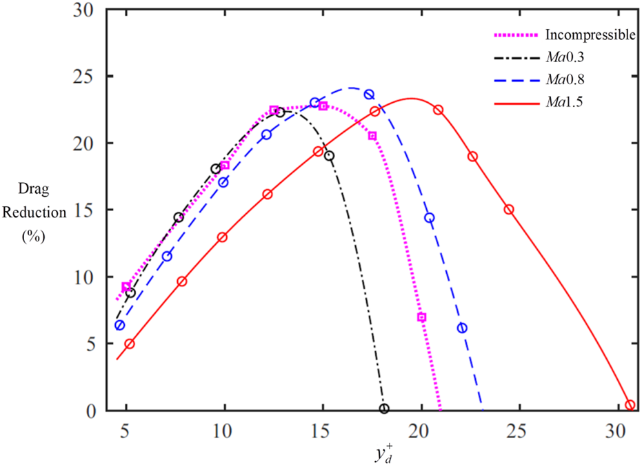
Drag reduction at different Mach numbers [49].
Blowing control only consumes a small amount of blowing energy, and can bring a certain amount of drag reduction. Currently, it has been verified that blowing can efficiently reduce drag, but the impact of flow characteristic parameters such as input Mach number, Reynolds number, etc. on the drag reduction is still a subject of debate. Furthermore, it is important to thoroughly comprehend the impact of blowing control strategies, such as blowing amplitude and frequencies, on the turbulent boundary layer.
Suction Control
The suction control in the boundary layer is a method of removing the low-kinetic-energy fluid near the wall to achieve the effect of suppressing boundary layer separation. Up to now, the suction control has been effectively applied in hypersonic intake ducts [50]. He et al. [51] employed suction slots to regulate the separation of the corner at a shock Mach number of Ma = 5.9. An observation was made that placing suction slots in the spanwise direction on the sidewall can effectively reduce the length of the shock wave train at the same back pressure. Additionally, removing low-momentum fluid near the corner can effectively ease the interaction between the shock wave and the boundary layer. As shown in Figure 11A, Sriram et al. [52] investigated the effect of wall suction on separation bubbles on a flat plate at free-stream Ma = 5.96, Re∞ = 4 × 10⁶ m−1 in wind tunnel experiments. They found that the suction control reduced the length of the boundary layer separation by 13.33%, which was depicted in Figure 11B, but it could potentially lead to enhancement of flow field instability. Subramanian et al. [53] conducted an experiment on the effects of suction control on hypersonic intakes at Ma = 2, Re∞ = 4.3×10⁷ m−1. They found that the suction pressure at the bottom of the groove could eliminate the formation of separation bubbles in the boundary layer, thus restoring the pressure losses caused by the shock/boundary layer interaction.
FIGURE 11
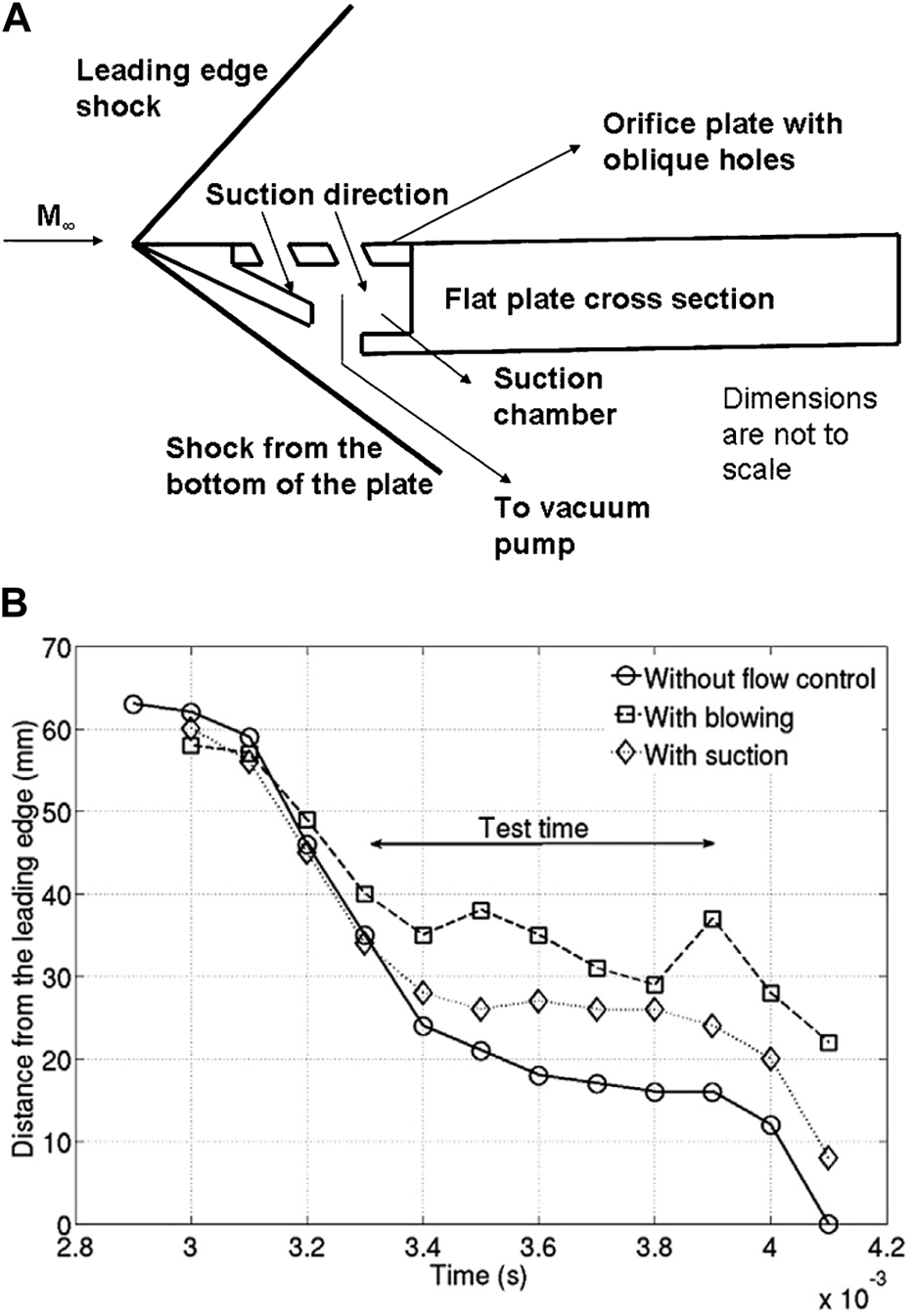
Schematic diagram of suction experiment by Sriram and Jagadeesh and the control effect [52]. (A) Schematic diagram of suction control experiment. (B) The separation location from the leading edge with and without control.
Suction control within the boundary layer is both straightforward and reliable, emerging as one of the most effective methods in contemporary engineering. By removing low-kinetic-energy fluid from the boundary layer, suction reduces flow loss due to separation and is frequently combined with blowing to enhance flow control. However, it also results in increased wall friction drag, leading to additional flow loss. Thus, finding an optimal balance between the benefits and drawbacks of suction remains a critical consideration.
Synthetic Jet Control
One kind of jet flow produced by a diaphragm oscillating inside a cavity is called a synthetic jet. Without the need for an outside airflow source, this oscillatory motion creates a number of vortex formations [54] that both intake and expels fluid, producing an air jet, as depicted in Figure 12. This technology is utilized in various applications, including cooling and flow control, owing to its effective manipulation of fluid dynamics. Hong et al. [56] provided a review of the geometric parameters influencing synthetic jet performance, which they categorized as: the aspect ratio of the rectangular orifice, the orifice depth, the cavity height, and the cavity diameter. Luo et al. [57] provided a comprehensive review to introduce the fundamental characteristics of synthetic jet actuators and their basic design principles applied in flow control for separated flow, intake ducts, thermal management, anti-icing, and underwater propulsion. Liu et al. [58] proposed a velocity-temperature coupling control method based on synthetic cold/hot jets on a supersonic flat-plate flow with Ma = 4.5, Re = 5,000. It was found that the temperature of the jet significantly affected the size of the unstable region and the growth rate of disturbance modes. As shown in Figure 13, the jet control changes the velocity and temperature of the boundary layer, which will affect the first mode and the second mode. Temperature fluctuations accelerated the transition from laminar to turbulent flow when the jet temperature was different from the incoming flow temperature. This led to a fuller velocity profile in the boundary layer, strengthened resistance to disturbances, and enhanced flow stability. Li and Zhang [59] proposed a novel hybrid synthetic jet actuator, which, compared to plasma synthetic jet actuators, exhibited higher peak velocity, gas refilling rate, and gas ejection rate. This method enhanced the duration and reliability of supersonic active flow control.
FIGURE 12
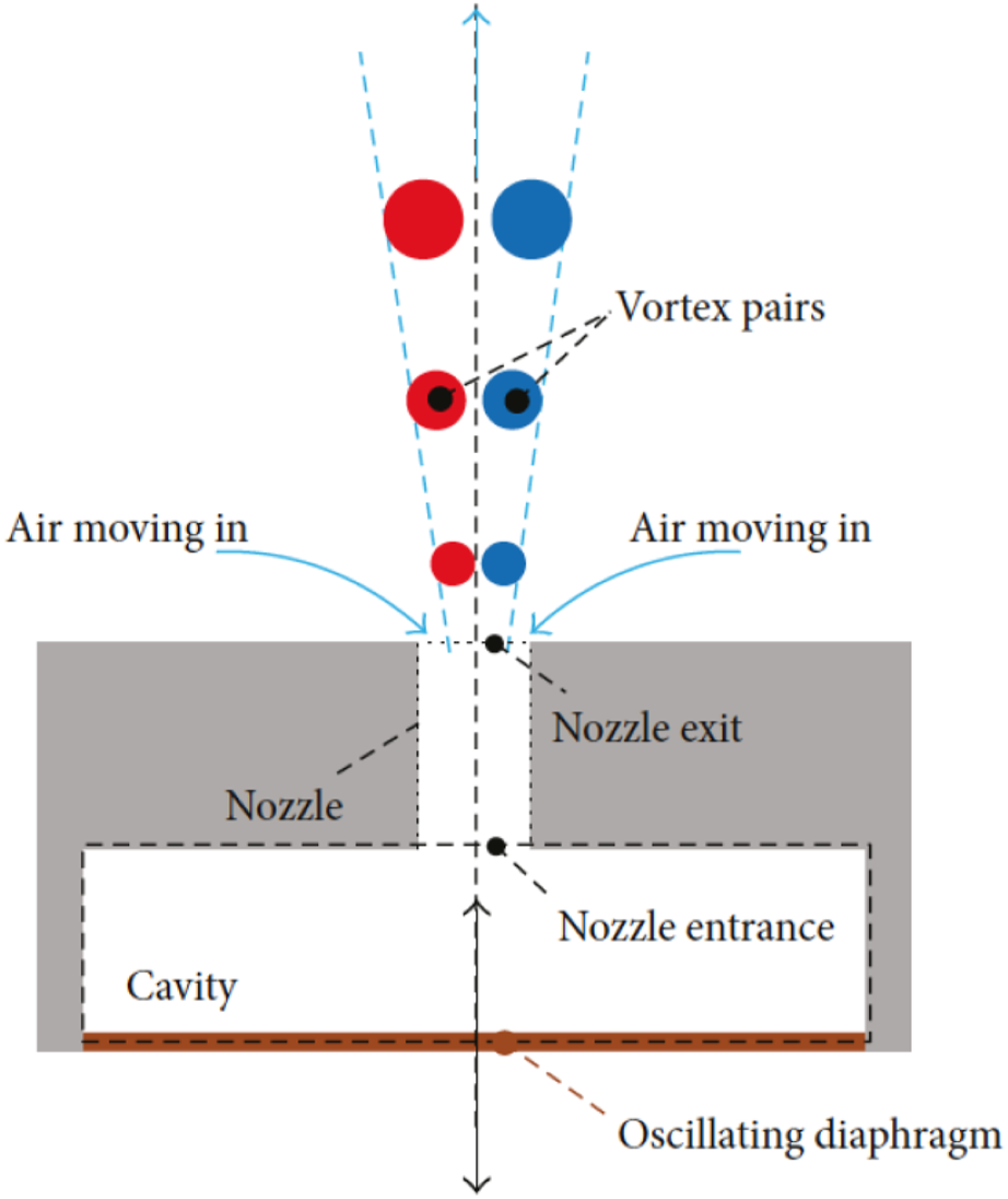
Schematic diagram of a synthetic jet actuator [55].
FIGURE 13
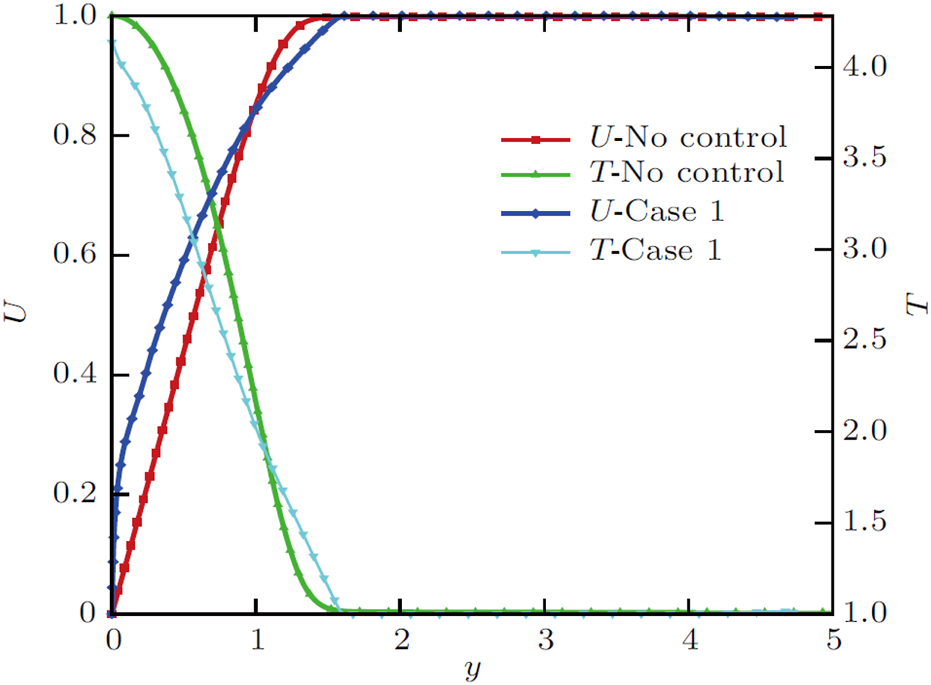
The comparison of velocity and temperature profile with and without control [58].
Synthetic jet control has the capability to improve the efficiency of momentum and energy transfer in jets, allowing for precision control over complex flow patterns. Also, it does not necessitate the introduction of external fluids, hence preventing any impact on the mass and energy equilibrium of the system. Furthermore, they exhibit little energy consumption and robust integration, making them suitable for a wide range of flow control scenarios. Nevertheless, synthetic jets encounter obstacles such as the synchronization and interference of jets, as well as issues with jet stability. They prove challenging to successfully manage flow separation on a wider scale or apply under hypersonic settings.
Microjet Control
Microjet control is a method for controlling jet arrays typically with a small diameter of the jet hole [60], as shown in Figure 14. At the freestream Ma = 2.0 and Re = 7.07 × 10⁶ based on the plate length, Verma and Manisankar [62] conducted an experimental study to investigate the effects of the spacing, pitch, and skew angles on the separation and shock unsteadiness. It can be seen from Figure 15 that the separation length XS is significantly reduced after using microfluidic control. The actuator produces pulsed high-speed microjets under Ma = 1.5, ReD = 8.5 × 10⁵ based on the cavity depth by exploiting the resonance of an impinging microjet source [63]. Additionally, the actuator’s resonant frequency may be actively regulated through the integration of intelligent materials into its structure. The microjets under freestream Ma = 2.9 approach utilizes the counter-rotating vortex pair (CVP) as its control mechanism [64]. This CVP is created by the microjet and serves to mix the low-energy flow within the boundary layer with the high-energy flow near the boundary layer. The magnitude of the vortex core in this controlled vortex pair is crucial for managing the SWBLI. The larger and more proximal vortex nucleus facilitates superior regulation of SWBLI.
FIGURE 14
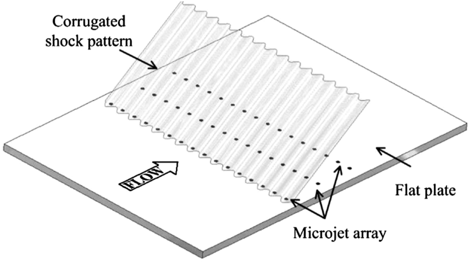
Schematic diagram of a microjet array [61].
FIGURE 15
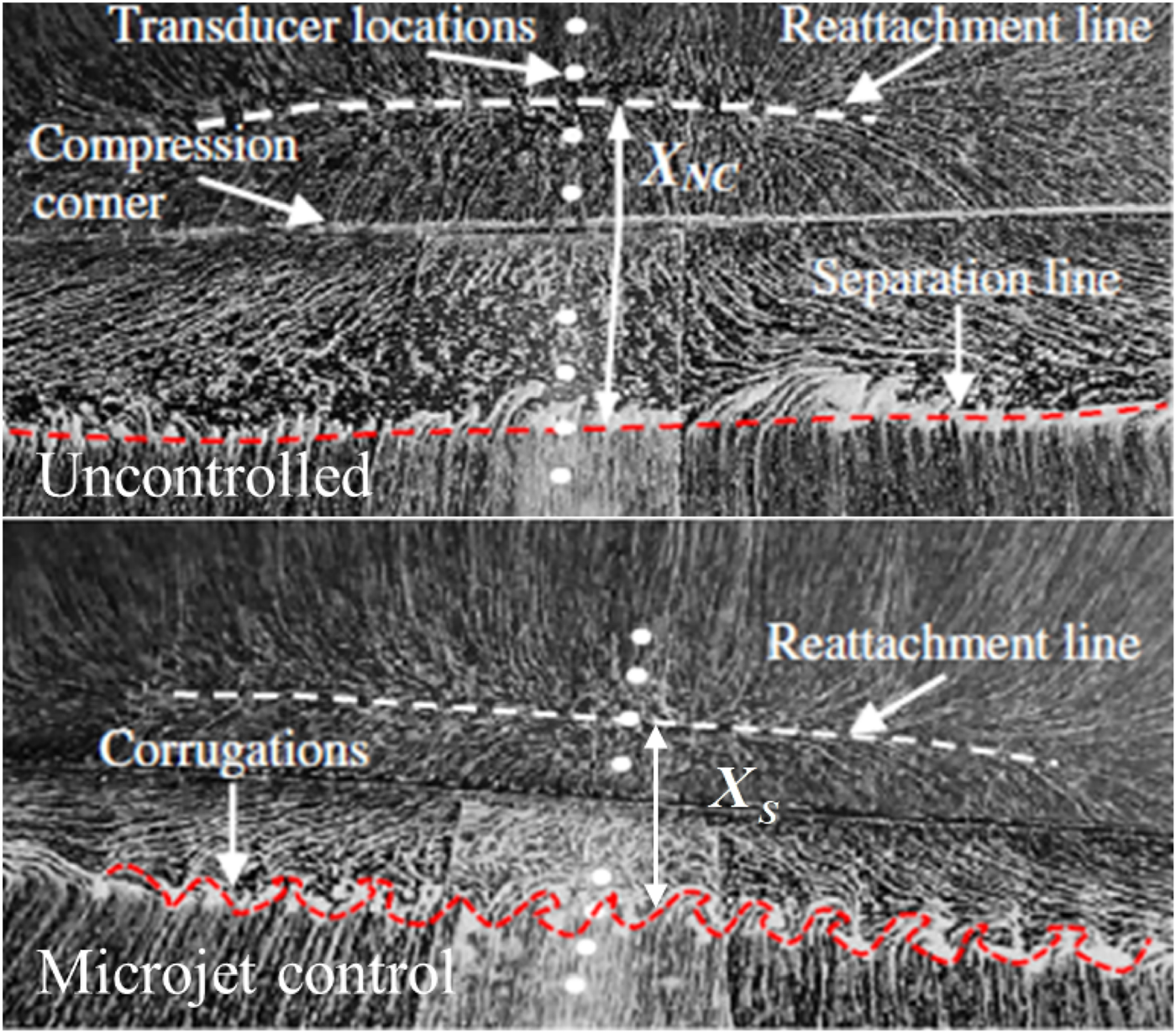
The comparison of surface oil visualization with and without control [62].
Microjet control effectively manages flow separation and stalling due to its high frequency and low mass flow rate, which enable rapid response to flow variations. However, it faces certain limitations. Managing large-scale flows is difficult because of the small action area of microjets. The effectiveness of the jet is highly sensitive to factors such as injection frequency, angle, and jet velocity, all of which must be meticulously adjusted to suit varying flow conditions. Despite these operational and technological constraints, microjet technology holds substantial potential for advancing flow control.
Plasma Control
Plasma control is a technology that involves using forms of discharge such as arcs to penetrate the gas within the boundary layer, to generate plasma and induce energy transport in the surrounding gas in order to suppress flow separation. Li and Wu [65] summarized the progress of the plasma excitation for flow control. They elaborated on the relevant principles, fundamental issues, flow control principles and methods. Additionally, they discussed applications in aircraft, engines, combustion, and made prospects for future development. The impacts of plasma synthetic jets on typical hypersonic flow in the consideration of the thermal perfect gas effect were studied by numerical simulations [66]. The results showed that during the first cycle after discharge, synthetic jets could reduce the average drag of the spherical head and increase the shock detachment distance, thus achieving flow control. Nanosecond dielectric barrier discharge (NS-BDB) was applied by Zheng et al. [67] to conduct experiments on a cylinder at Ma = 4.76. As shown in Figure 16, they discovered that the micro shock wave produced by plasma discharge interacted with the detached shock wave, causing the bow shock wave in front of the cylinder to move forward. At the same time, the plasma changed the pressure distribution near the cylinder, reducing the drag by 8.3%. Wang et al. [68] used NS-DBD plasma actuation for flow control (Ma = 1.5, Re = 1.8 × 10⁵∼2.7 × 10⁶) and found that such actuation induces a distorted flow structure on the suction surface of the blade, thereby enhancing shock wave oscillations in the blade passage and suppressing flow separation on the pressure surface. By introducing the research history and specific applications of Pulsed Plasma Synthetic Jets (PPSJ), Russell et al. [69] concluded that the working conditions of high frequency and actuators may be areas for further research in the future, and that a standard needs to be established to determine the impact of the geometric shape of actuators on PPSJ performance.
FIGURE 16

The detached shock wave moves away from the cylinder caused by plasma discharge [67]. (A)t = 0. (B)t = 1μs. (C)t = 4μs. (D)t = 7μs. (E)t = 11μs.
The primary advantage of plasma control lies in its ability to achieve contactless fluid control, thereby circumventing the complexities associated with mechanical installation and potential interference. Additionally, plasma control offers rapid response capabilities and the ability to adjust the flow field in real time. However, maintaining and controlling plasma over a large flow field demands substantial energy and sophisticated equipment, which limit the application of plasma in engineering. Despite these limitations, the plasma control technology possesses significant potential for future development.
Energy Deposition Control
Energy Deposition (ED) is a method of introducing energy into the front part of an aircraft by means of techniques like electrode discharge, laser excitation or sparkjet. Figure 17 shows the three stages of sparkjet operating cycles. The purpose of this is to modify the configuration of shock waves and airflow properties at the aircraft’s nose, resulting in a decrease in aerodynamic drag produced by shock waves [71]. The mechanism of energy deposition was consisted of three main steps [72]: the formation and deformation of high-temperature plasma, the interaction between high-temperature plasma and bow shock, and the recovery of pressure and heat flux at the nose of the aircraft. Among these steps, the interaction between plasma and shock waves is the key to drag reduction. Additionally, the main parameters affecting energy deposition can be categorized as deposition energy, deposition location, energy repetition frequency, and freestream Mach number. Xie et al. [73] used SparkJet (SPJ) to control the shock wave interaction of high-enthalpy flow at Ma = 6.9. The experimental results revealed that within a certain range, the control effect of SPJ on ramp shock waves continued to improve with the increase of pressurized cavity pressure, ramp distance and the decrease of ramp inclination angle. As pictured in Figure 18, SPJ shock decreased the Mach number, leading the sonic line move upward, which weakened the ramp shock wave. Azarova et al. [74] suggested implementing drag force control through the utilization of multiple energy sources within the supersonic shock layer (Ma = 1.89∼3.45). The utilization of multiple energy sources led to a decrease in frontal drag force by 19% for a blunt cylinder and 52% for a hemisphere-cylinder.
FIGURE 17
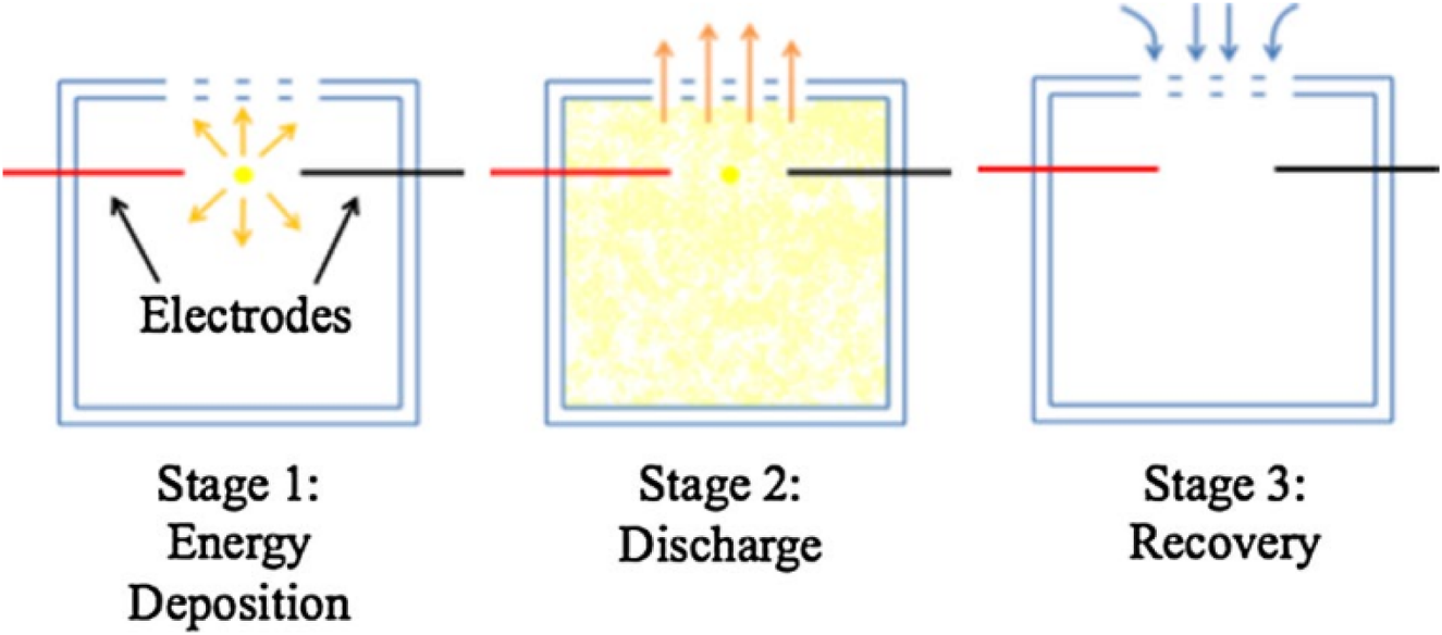
Three stages of Sparkjet operating cycle [70].
FIGURE 18
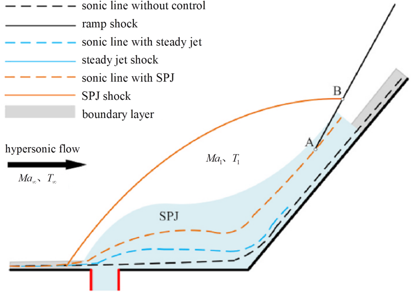
Shock waves and sonic lines with and without control [73].
Energy deposition has excellent instantaneous response capabilities and wide applicability, and can change flow characteristics by rapidly heating the fluid. Nevertheless, energy deposition flow control also faces significant challenges. Energy deposition technology has high energy requirements. In addition, it is prone to unstable phenomena in practical applications, such as local overheating or uncontrollable changes in the shock wave structure, which may lead to unstable flow control effects. Therefore, further research is needed due to the complicated nature of the system, expensive costs, and unique properties such as ionization and chemical reactions generated by high-energy fluid [75].
Magnetohydrodynamic Control
Magnetohydrodynamic (MHD) control is a method of controlling fluids by the interaction between magnetic field and conducting fluid. Zhang et al. [76] provided an overview of the application of MHD control in hypersonic flow. They focused on three major MHD techniques: 1) large-scale flow control to expand the flight envelope in terms of Mach number and angle of attack, 2) near-surface flow control to mitigate shock wave/boundary layer interactions, and 3) leading-edge heating-transfer control to manage enormous thermal loads on the leading edge of compression ramps. As shown in Figure 19A, Jiang et al. [77] employed the k-ω SST model to conduct a numerical investigation on the impact of various magnetic field and plasma combinations on SWBLI at Ma = 5.0, Re∞ = 3.67 × 10⁷ m−1. The utilization of electromagnetic control enhances the energy of the boundary layer, and the pressure gradient within the separation bubble is of comparable magnitude to the exerted electromagnetic force. The largest separation reduction reached 0.296 as illustrated in Figure 19B. The effectiveness of MHD control in separated flow at Ma = 14.1, Re∞ = 2.32 × 10⁵ m−1 was found by Luo et al. [78] to be mostly dependent on the streamwise direction of the Lorentz force’s flow acceleration. It is possible to accelerate the low-velocity fluid in the boundary layer by introducing an external electromagnetic field. Additionally, there was a perfect place to apply the MHD zone, which could totally remove flow separation from the surface.
FIGURE 19
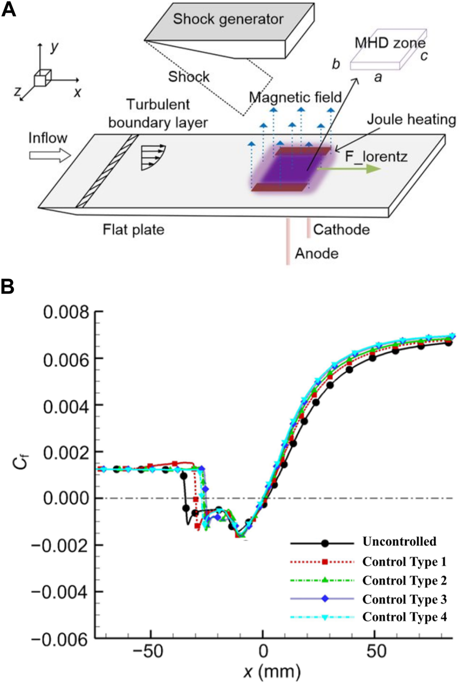
Magnetohydrodynamic experiments in SWBLI [77]. (A) Schematic diagram of MHD experiment. (B) Wall skin friction coefficient distributions of uncontrolled and four control types. Control type 4 reached the largest drag reduction.
MHD is a non-contact control technology that reduces mechanical friction loss and the resultant additional resistance, and can be used in some extreme environments with high temperature and high pressure. However, at the same time, MHD flow control consumes a lot of energy to generate and maintain a strong magnetic field. Therefore, how to save energy as much as possible while ensuring the effect of MHD flow control is an important issue in future research.
Passive Control
Micro Vortex Generator Control
Micro Vortex Generator (MVG) control is a method that utilizes streamwise vortices to attract high-momentum fluid into the boundary layer, hence improving its ability to resist flow separation [79]. Four types of micro vortex generators are shown in Figure 20. The impacts of MVG arrays at Ma = 7.0, Re = 5.03 × 10⁶ were numerically calculated by employing the DES model [81]. The results showed that the MVG arrays have a significant impact on the boundary layer of hypersonic fluids. This leads to a decrease in the size of separation bubbles, a reduction in the intensity of separation shock waves, and an increase in the velocity gradient in both the separation bubbles and the downstream fluid. As a result, there is a potential reduction in total pressure losses of up to 1.9%. Zhu and Wang [82] discovered that at Ma = 2.0, placing the jet after the MVG can greatly improve the ability of the isolated segment to withstand backpressure, resulting in better flow control performance. Gnani et al. [83] mentioned that compared to traditional generators, MVGs, while increasing parasitic drag, still offer advantages in generating a slightly thicker boundary layer and reducing drag. Experimental methods such as schlieren photography, surface flow visualization, and infrared thermography were used by Saad et al. [84] to study the effect of micro-ramps on the shock wave/boundary layer interaction at Ma = 5. As illustrated in Figure 21, the experiment confirmed that the presence of micro-ramps delayed the pressure rise, reduced the upstream interaction length, and thus suppressed the shock wave/boundary layer interaction.
FIGURE 20
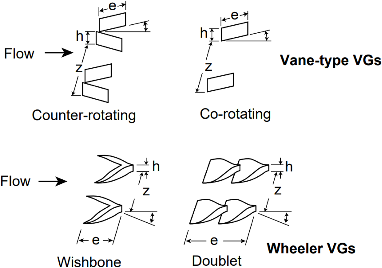
Types of micro vortex generators [80].
FIGURE 21
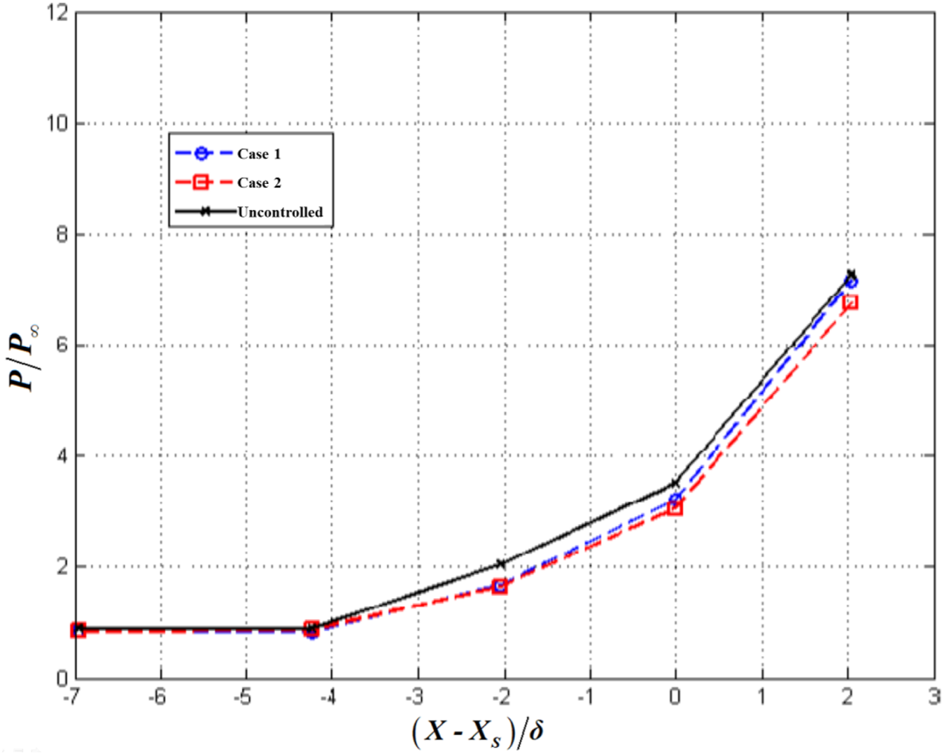
Pressure distribution in the streamwise direction with and without control [84].
MVGs are used to manipulate airflow over surfaces to enhance aerodynamic performance. They are much smaller than conventional vortex generators, often only a few millimeters in size, and are strategically placed on the surface of an aircraft or other vehicles to control the boundary layer, reduce drag, delay flow separation and improve overall efficiency. Despite the benefits, MVGs must be carefully designed and placed to avoid adverse effects such as increased turbulence or noise. The design of MVGs requires precise aerodynamic analysis to ensure they provide the intended benefits without introducing new issues.
Aerospike Control
As shown in Figure 22, Aerospike control utilizes a pointed rod mounted on the nose of an aircraft to increase the standoff distance of the bow shock and to transform the strong bow shock into an oblique shock, with the aim of drag reduction [85]. Guan et al. [86] set up an incoming flow condition with Ma = 2.2 and ReD = 2.6 × 10⁵ based on nose diameter to test four types of aerospikes under zero and non-zero angles of attack. The measurement results processed by three statistical methods indicated that the aerospikes effectively suppressed airflow fluctuations under any angle of attack tested in the experiment. As shown in Figure 23, Deng et al. [87] studied the aerodynamic performance of disk spikes in a hypersonic flow (Ma = 8.0). Their results indicated that using a hemispherical disk spike at the nose, with a spike length-to-nose diameter ratio (L/D) of 2, provided the optimal drag reduction effect. At an 8° angle of attack, the maximum drag on the nose and the entire vehicle was reduced by 49.3% and 4.39%, respectively. Another study [88] proved that an aerospike with the aspect ratio of 4 at a Ma = 7.0 flow has the capability to diminish the impact body’s resistance by 52.57%. According to Xu et al. [89], the aerospike with a cone shape exhibited the least effective reduction in drag and heat. In contrast, the aerospike with a flat profile demonstrated the highest heat reduction and the hemispherical aerospike the highest drag reduction. Elevating the aspect ratio of the aerospike results in a substantial improvement in both its resistance to heat and drag.
FIGURE 22
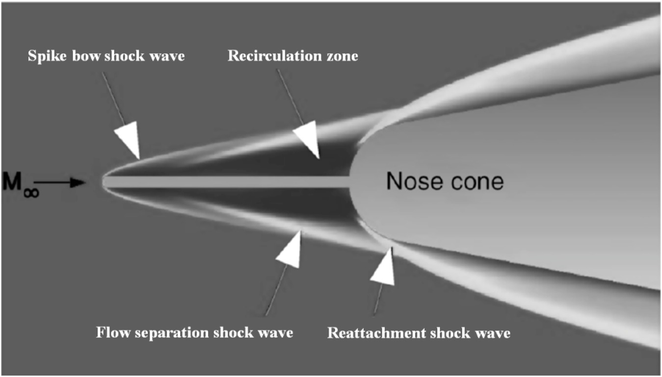
Aerospike-induced flow field [85].
FIGURE 23
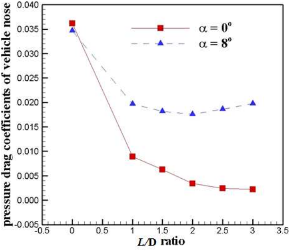
Pressure drag coefficients of vehicle nose varies with L/D ratio of spike [87].
Aerospike control is advanced aerodynamic devices used primarily for flow control in hypersonic application. In practical applications, aerospike control provides a straightforward configuration that obviates the necessity for an extra energy provision system, thereby efficiently diminishing drag. Unlike traditional control surfaces like fins or flaps, aerospikes are pointed structures that extend forward into the flow, manipulating the shock waves and boundary layers to enhance stability, reduce drag, or control flow separation at extremely high velocities. At the same time, at hypersonic speeds, aerospikes are subjected to extreme aerodynamic and thermal stresses, so consideration must be given to the thermal protection of aerospikes in high-temperature environments. Ensuring the structural integrity and thermal resistance of the aerospike is a significant design challenge.
Riblet Control
Riblet control is inspired by shark skin and utilizes micro-sized, serrated structures on the surface to achieve drag reduction and noise mitigation. Generally, there are six kinds of riblet configurations, as listed in Figure 24. Ran et al. [91] computed a steady-state covariance matrices that allow for examining the impact of riblets on the dominant turbulent structures. The study shows that at small scales, triangular riblets limit the wall-normal momentum transfer associated with near-wall cycle and the generation of secondary flow structures around the riblet tips. Riblet-equivalent boundary conditions on smooth computational walls were introduced by Li et al. [92] to simplify the difficulties associated with numerical simulations. The effectiveness of the association between non-dimensional geometric parameters and wall roughness has been established by experimental investigation at Ma = 0.4. Applying the riblet model to a particular missile resulted in a 2.4% decrease in the total drag coefficient and a 3.4% reduction in surface friction. Zhou et al. [93] conducted a study on the impact of riblets at Ma = 6.0 and Re∞ = 1×10⁷ m−1. They discovered that riblets have the ability to affect the turbulent surface friction by suppressing or disturbing large-scale vortex formations. The drag reduction rises as the groove height grows and the distance between grooves reduces, within a suitable range. Wen et al. [94] experimentally assessed the effects of chevron-shaped grooves on the interaction between shock waves and turbulent boundary layers at Ma = 1.85 and Re∞ = 1.26 × 10⁷ m-1. As shown in Figure 25, the pressure distribution curves indicate that the riblet control delays the rise of surface pressure compared with the uncontrolled case. This is because the boundary layer downstream of the riblet center is thinner, the extent of flow separation is extenuated, and it is closer to inviscid flow.
FIGURE 24
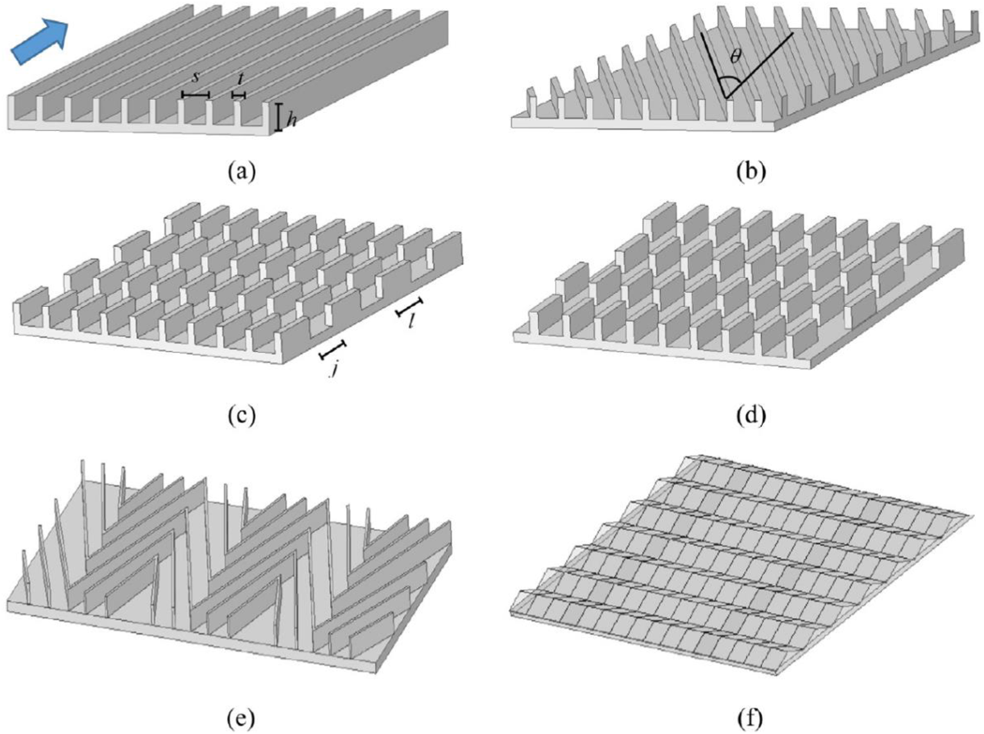
Catalog of riblet configurations [90]. (A) continuous longitudinal. (B) continuous in yaw. (C) inline segmented. (D) staggered segmented. (E) herringbone. (F) zigzag.
FIGURE 25
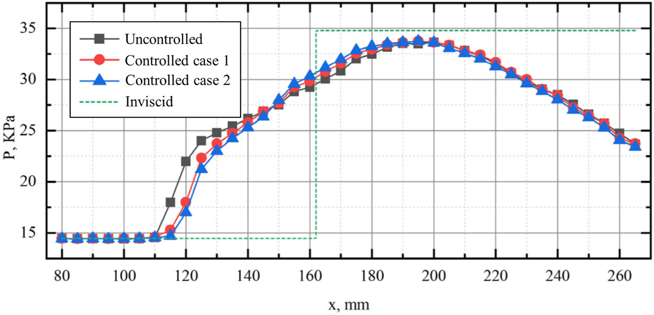
Comparison of streamwise surface pressure distributions in the controlled and controlled cases [94].
Riblet control is a highly effective drag reduction technique that leverages microscopic surface textures to manipulate turbulent flow near a surface. By reducing skin friction drag, riblets offer significant performance and efficiency gains in aerospace, marine, and various industrial applications. However, riblet surfaces can be prone to damage from abrasion, fouling, or environmental exposure, which can diminish their effectiveness. Maintaining the integrity of riblet structures is crucial for sustained performance.
Research Methods of Flow Control
High-Speed Computational Fluid Dynamics
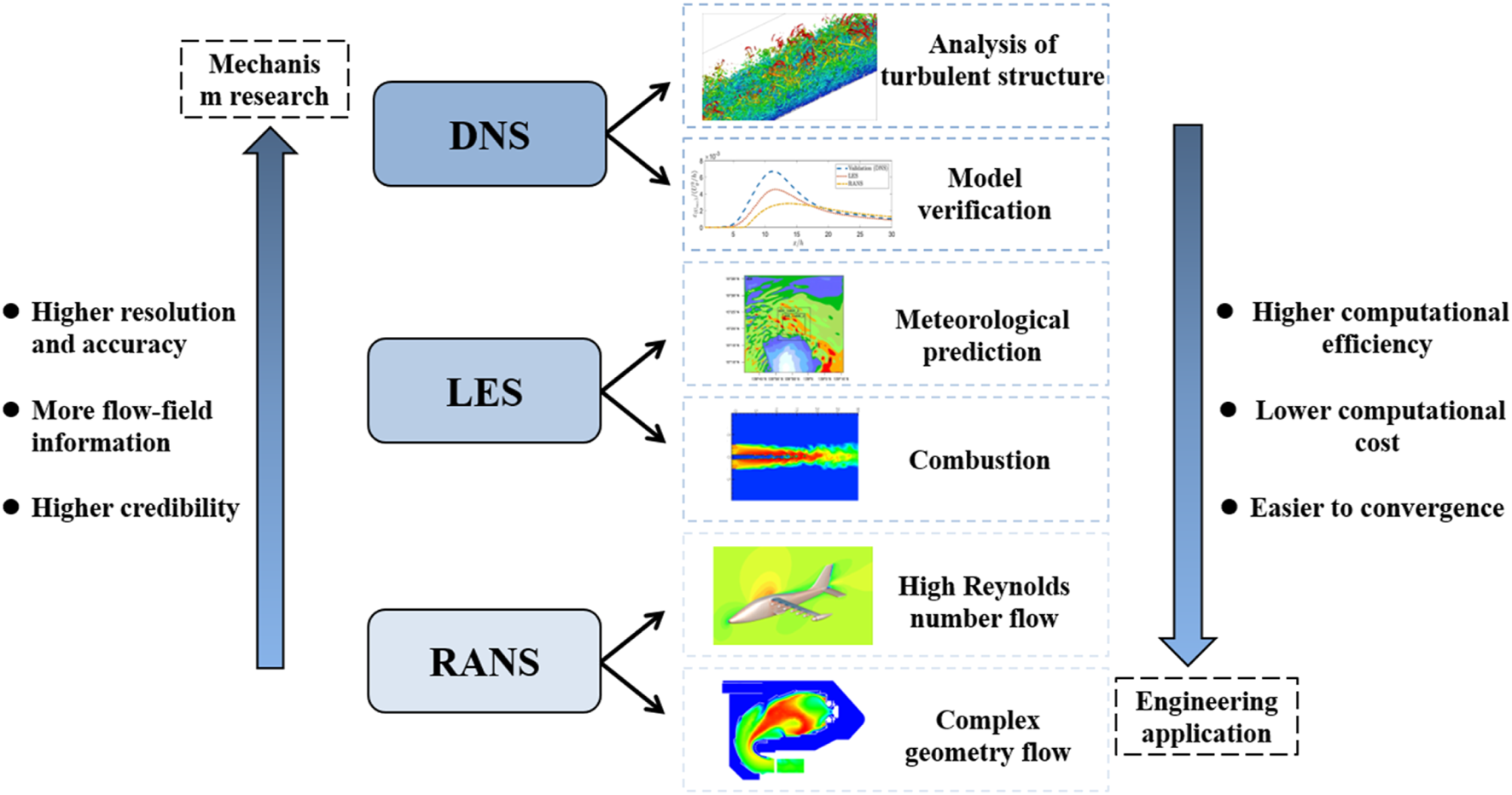
As shown in Figure 26, the numerical methods employed for simulating high-speed flow primarily consist of direct numerical simulation (DNS), Reynolds-averaged Navier-Stokes simulation (RANS), and large eddy simulation (LES). The DNS directly solves the discretized Navier-Stokes equations, yielding very comprehensive information about the flow field. This includes time series data of three-dimensional flow fields, spatial structures of turbulence, as well as time-averaged values and fluctuations of specific flow variables. To address the upwind issue in the convective term of the Navier-Stokes equations, various approaches have been developed. These include flux vector splitting techniques such as Steger-Warming, Lax-Friedrich, Van Leer, as well as flux difference splitting schemes like Roe and HLLC. Shock-capturing techniques with high accuracy include the WENO, NND, GVC and WCNS. For high-enthalpy hypersonic flows, due to chemical non-equilibrium effects, there exists a weak coupling relationship between the vibrational energy of gas molecules and pressure. The shock sensors proposed by Jameson [100] or Ducro [101] are no longer applicable. Passiatore et al. [102] enhanced the shock sensor by replacing pressure variables with vibrational temperature, resulting in the effective detection of shock waves and contact discontinuities. Pirozzoli [103] identified several concerns about discontinuous regions. Overcoming Gibbs phenomena and integrating artificial dissipation continue to be difficult for DNS.
The advantage of the RANS method lies in its allowance for larger grid scales, which reduces computational costs significantly. However, it is necessary to develop models for the Reynolds stress terms. There are various prominent turbulence models, such as the k-ε model, the k-ω model, the SST model, and the S-A model. Knight and Degrez [104] performed a comprehensive evaluation of turbulence models for analyzing SWBLIs using RANS. The findings revealed that each turbulence model has a specific range in which it is suitable, and simulating flows with distinct characteristics could lead to substantial inaccuracies. Fu and Wang [105] summarized the RANS model for high-speed flows and proposed a RANS model with wider applicability and better robustness. The fundamental idea behind the LES approach is that small- and large-scale vortices are separated by the filter function, with the small-scale vortices being modelled and the large-scale vortices being solved directly [106–109]. This method’s computing cost lies in between the other two numerical approaches since it may be thought of as a hybrid of the DNS and RANS methods.
Supersonic and hypersonic flow control often involves dealing with complex geometric boundaries, such as grooved surfaces, wavy walls and porous media. Studying such problems should not directly employ real geometric boundaries for computation. Instead, it’s preferable to model and handle these boundary conditions equivalently. Wang et al. [110] utilized an aperture-type acoustic metasurface model for equivalent treatment, thereby avoiding the need to solve complex geometric boundaries and simplifying the computation process. Zeng et al. [111] employed a channel flow DNS program combined with the immersed boundary method to model and simulate flow over non-smooth blade surfaces in real-world scenarios, considering parameters such as arithmetic mean height, roughness, and effective slope. Ghosh et al. [112–114] employed the immersed boundary method (IBM) and a hybrid RANS/LES approach to solve for flow phenomena related to shock-boundary layer interactions.
With the rapid development of parallel computing technology, CFD methods have become increasingly imperative and gradually served as a mainstream approach in flow control research. Utilizing CFD methods for flow control in drag reduction and thermal protection applications enables the calculation of physical quantities that may be difficult or impossible to measure experimentally, and provides rapid access to flow information, which demonstrates strong flexibility. However, this method also has its limitations. For instance, the accuracy of CFD methods relies on the accuracy of the computational models and the applicability of the assumptions made, hence it is important to consider beforehand whether the selected model is suitable for the intended application.
Wind Tunnel Experiments
Wind tunnel experiments are a critical tool for investigating high-speed flow control. By placing scale or subscale models within a wind tunnel, equipped with various sensors and flow visualization instruments, these experiments can simulate the real flow situations. Here are some famous hypersonic wind tunnels illustrated in Figure 27. Liu et al. [119] conducted a review of experiments on the receptivity stage and the linear growth stage of hypersonic boundary layer transition. The Supersonic Nano-tracer Planar Laser Scattering (NPLS) approach was described by Yi et al. [120] Based on this principle, further techniques for detecting density fields, Reynolds stress, and aerodynamic optics were also developed. A survey of flow control techniques for reducing heat and drag in supersonic and hypersonic flows [121] was conducted, including forward-facing cavities, counter-flowing jets, aerospikes, and energy deposition, as well as the advancements in experimental studies pertaining to their combination. Berry et al. [122] carried out experiments on the effect of multiple porous models of the Hyper-X on boundary layer transition. The findings confirmed that the configurations with serrated grooves or a single row of large holes can effectively force a boundary layer transition. Borg and Schneider [123] placed a 20% scale model of the X-51A fore-body in a quiet wind tunnel and equipped it with a trip wire. They discovered reducing the noise level of freestream could increase the transition Reynolds number by 2.4 times, significantly affecting the transition caused by roughness. As demonstrated in Figure 28, Zhu et al. [124] investigated the impact of the jet on the aerodynamic performance of the airfoil at various angles of attack in a Ma = 5.0 hypersonic wind tunnel. The findings indicated that manipulating the jet has a positive impact on the lift and pitch torque coefficients, and this effect becomes more pronounced as the jet outlet flow rises at each angle of attack. Xia et al. [125] studied the effects of Ramp-VG array (ramp vortex generator array, RVGA) on the supersonic mixing layer. The results confirm that RVGA can improve the energy distribution in the supersonic mixing layer, achieving the performance of increasing flow velocity and delaying transition.
FIGURE 27
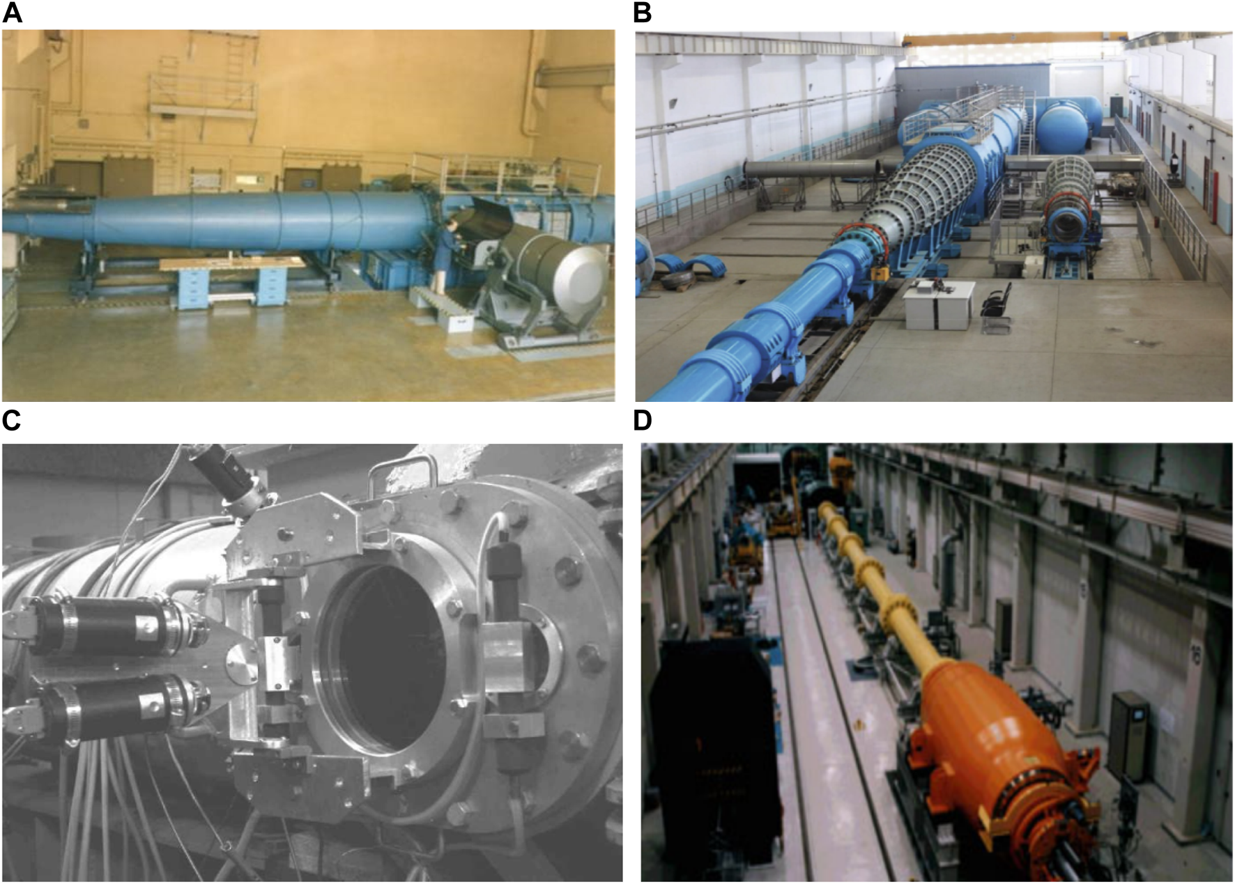
Some hypersonic wind tunnels over the world. (A) AEDC T9 [115] (B) IMCAS JF-12 [116]. (C) TsAGI UT-1M [117] (D) JAXA HIEST [118].
FIGURE 28

Schlieren images at different angles of attack [124].
In the past few years, supersonic and hypersonic wind tunnels have achieved significant progress, with the advent of high-enthalpy wind tunnels, shock wind tunnels and gun wind tunnels, making a further enhancement in the modeling capabilities of wind tunnel experiments. Nevertheless, there is still potential for further progress in wind tunnel tests. There is a need to enhance the manufacturing capabilities and precision of models, as well as to systematically address the effects caused by scale factors. However, it is imperative to optimize the efficiency of wind tunnels in order to simulate a wide range of flow environments.
Aircraft Flight Tests
Although numerous studies have explored flow control in high-speed fields, practical engineering applications in aircraft is still limited. This discrepancy highlights a gap between theoretical advancements and their implementation in practical flying scenarios [126]. This gap can be attributed to several factors, including the complexity of integrating flow control technologies into existing aircraft designs, the high cost of development and testing, and the challenges associated with scaling laboratory results to full-scale applications.
Choosing suitable flow control techniques for an aircraft’s transition in-flight is challenging because of the variations in flow conditions between flight and being on the ground. Without actual flight data as a reference, it becomes impossible to make accurate decisions. Consequently, numerous countries are currently engaged in active hypersonic boundary layer transition flight tests in order to get further flow data that corresponds to these tests. As shown in Figures 30A, B, the United States, in conjunction with Australia, launched the HIFiRE-1 [127] and HIFiRE-5b [128] vehicles in 2010 and 2016, respectively. HIFiRE-1 is a blunt cone with zero angle of attack, a half-cone angle of 7°, and a head radius of 2.5 mm, flying at Mach numbers ranging from approximately 3.04–5.79. HIFiRE-5b is an elliptical cone with a short axis half-angle of 7°, an aspect ratio of 2:1, and a head radius of 2.5 mm. It can be clearly seen from Figure 29 that there is a significant discrepancy between the real transition Reynolds number of HIFiRE-5b and the wind tunnel experimental results. As shown in Figures 30C, D, two vehicles, the MF-1 [130] and HyTRV [131], were launched in China in 2015 and 2019, respectively, and are used to collect transition data for blunt cones with a small angle of attack and lifting bodies with a variable angle of attack at hypersonic speeds. These data provided information on pressure, heat flux, and unstable wave amplitudes under different flow situations.
FIGURE 29
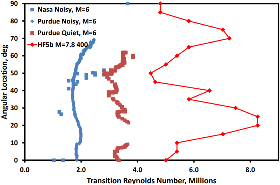
Comparison of transition Reynolds number of HIFiRE-5b and wind tunnels [129].
FIGURE 30
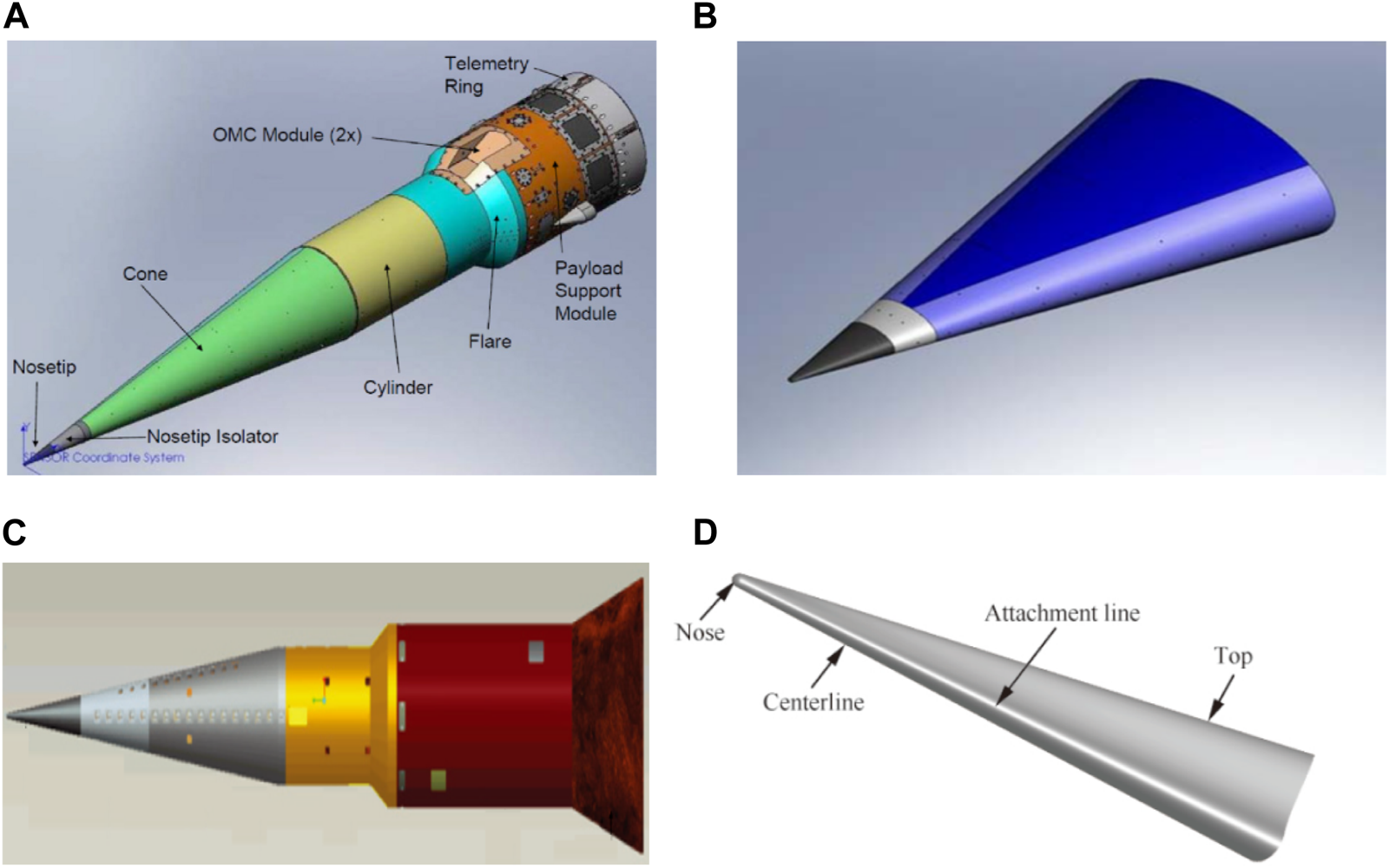
Schematic diagrams of flight tests of hypersonic boundary layer transition. (A) Schematic diagram of HIFiRE-1 [127]. (B) Schematic diagram of HIFiRE-5b [128]. (C) Schematic diagram of MF-1 [130]. (D) Schematic diagram of HyTRV [131].
In some flight tests, attempts have been made to employ active flow control designs. A collaborative effort involving the United States, France, and other countries was conducted in the HyShot program, aimed at exploring the basic performance of scramjet engines at high Mach numbers. In 2002, the HyShot II [132] experiment was conducted, utilizing a fixed-geometry two-dimensional inlet with suction devices in the inlet to ensure its initiation. Active flow control could also enhance rudder authority by reducing airflow separation during large rudder deflections and significant sideslip angles. In 2015, Boeing and NASA [133] tested a pneumatic sweeping-jet-based active flow control system on the modified Boeing 757 eco Demonstrator. The flight test data suggested that the flow control actuation might be able to provide an approximately 14% increase in side force at the maximum tested rudder deflection and at critical sideslip angles.
In addition, some flight experiments achieved passive control by altering the flow profile through the installation of aerospikes or quiet spikes. For example, aerospikes were utilized on the HIFiRE 7 aircraft [134]. Gulfstream and NASA [135] installed multi-stage quiet spikes in front of the F-15B nose, conducting multiple flight tests in the range of from Mach 0.8 to 1.8. It was found that the quiet spikes successfully attenuated the strong shock waves at the nose into a series of weaker shocks, effectively reducing the sonic boom. The X-43A aircraft used rough strips [136] at the front end of the air inlet to induce forced transition of the boundary layer and lessen the sensitivity to flow separation. Saric et al. [137] conducted a study on the infrared thermal imaging results of the swept wings of the F-15B aircraft at Ma = 1.85. They discovered that the inclusion of periodic discrete roughness elements can increase the laminar flow area to 70%∼80% and reduce drag by 20%∼25%.
Flight experiments remain the most genuine and dependable step for pushing flow control to practice application. Given the exorbitant expenses associated with flight experiments, it is imperative to explore various methods to mitigate these expenditures. However, it is crucial to extract the maximum amount of relevant information from the minimal flight data that is accessible. Furthermore, it is imperative to enhance the sophistication and dependability of measurement instruments and sensors, while consistently investigating the potential for combining flying experiments with other research methodologies. As a result, while research continues to advance the theoretical understanding of flow control, translating these innovations into practical solutions for aircraft requires overcoming significant technical and economic hurdles. Addressing these challenges could potentially lead to enhanced performance, fuel efficiency, and overall safety in future aerospace vehicles.
Conclusion
Supersonic and hypersonic flows play a crucial role in the study of fluid dynamics at high speeds. This study provides an overview of the typical physical phenomena, flow control strategies, and research methodologies related to two specific flows. Several studies have been conducted on flow phenomena that are specific to supersonic flow, including the previously mentioned boundary layer transition, shock waves, and sonic explosions. Nonetheless, translating the present research discoveries into tangible implementations for flow control presents a formidable obstacle. It is also important to consider the potential interactions that may occur between these phenomena, such as boundary layer transition interference and shock waves.
Active flow control methods consist primarily of plasma control, jet control, energy deposition control, magnetohydrodynamic control, and others; these techniques are distinguished by their superior performance and high efficiency. These methodologies offer a means to dynamically adjust and enhance the metrics in response to real-time flow conditions, with the ultimate goal of achieving optimal flow efficiency. Notwithstanding its merits, active control continues to encounter challenges that require future resolution, including but not limited to relatively elevated expenses, technological intricacy, and the possibility of substantial energy downfall. Conversely, passive flow control systems, such as aerospike control, riblets control, micro vortex generator control, and others, are distinguished by their cost-effectiveness and dependability. Given that these techniques do not require the addition of additional energy, they offer the advantages of energy conservation and environmental protection. Nevertheless, due to the fact that regulation is accomplished by modifying flow shapes, the control efficacy might be susceptible to the fluctuations of fluid dynamics. In the future, endeavors ought to be concentrated on improving the geometry and properties of passive flow control in order to accommodate a more extensive flow scenario.
Common research methodologies for supersonic and hypersonic flow control include flight testing, numerical simulation, and wind tunnel experiments. Although numerical simulation is generally more cost-effective and can generate vast amounts of detailed data for a variety of flow conditions, capturing flows with a high Reynolds number precisely frequently necessitates substantial computational resources. Experiments in wind tunnels provide a means to directly observe the flow and acquire comprehensive results. On account of the scale effect and additional variables, discrepancies between these results and actual flow are possible. Flight testing has the potential to yield the most precise and dependable data for directly evaluating the efficacy of flow control. Large-scale implementation, however, is both impractical and prohibitively costly. As a result, each of the three approaches possesses distinct merits and demerits. Future research must incorporate careful consideration of the study’s focus, while also evaluating the merits and drawbacks of each approach in order to determine the most appropriate one.
Statements
Author contributions
SL: Writing, Review, Editing, Original draft. YZo: Writing, Editing, Investigation, Original draft. JL: Review, Formal analysis. JZo: Review, Formal analysis. JZh: Resources, Investigation. YZe: Resources, Project administration; Supervision. YZa: Review, Editing, Investigation, Supervision. All authors contributed to the article and approved the submitted version.
Funding
The author(s) declare that no financial support was received for the research, authorship, and/or publication of this article.
Conflict of interest
The authors declare that the research was conducted in the absence of any commercial or financial relationships that could be construed as a potential conflict of interest.
References
1.
Tishkoff JM Anderson JD . Breaking the Sound Barrier. In: AIAA Scitech 2019 Forum, January 7–11, 2019, San Diego, CA, (2019). p. 2194. 10.2514/6.2019-2194
2.
Abdulrahman GA Qasem NA Imteyaz B Abdallah AM Habib MA . A Review of Aircraft Subsonic and Supersonic Combustors. Aerosp Sci Technol (2023) 132:108067. 10.1016/j.ast.2022.108067
3.
Duan L Beekman I Martin M . Direct Numerical Simulation of Hypersonic Turbulent Boundary Layers. Part 3. Effect of Mach Number. J Fluid Mech (2011) 672:245–67. 10.1017/S0022112010005902
4.
Chen JF Xu Y Xu XB Zou QF Ling G Zhang YF. Pressure Fluctuation Experiments of Hypersonic Boundary-Layer on a 7-Degree Half-Angle Sharp Cone. J Exp Fluid Mech (2023) 37(6):51–60. 10.11729/syltlx20210054
5.
Candler GV . Rate Effects in Hypersonic Flows. Annu Rev Fluid Mech (2019) 51:379–402. 10.1146/annurev-fluid-010518040258
6.
Song XX Zhang S Zhang JF Zheng Y . Study on the Variation of Gas Radiation Characteristics of Hypersonic Reentry Vehicles. AIAA J (2023) 61(12):5277–87. 10.2514/1.J063001
7.
Tsien HS . Similarity Laws of Hypersonic Flows. J Math Phys (1946) 25:247–51. 10.1002/sapm1946251247
8.
Zhang Y Ye ZX Li BH Xie L Zou J Zheng Y . Numerical Analysis of Turbulence Characteristics in a Flat-Plate Flow With Riblets Control. Adv Aerodyn (2022) 4:29. 10.1186/s42774-022-00115-z
9.
Zhang Y Zhao YL . Novel Design of a Circulation Control Airfoil With Cylinder Rotation. Phys Fluids (2023) 35:085113. 10.1063/5.0158974
10.
Xie L Li BH Zhang Y Zheng Y Zou J . Effects of Temperature on Drag Reduction in a Subsonic Turbulent Boundary Layer via Micro-Blowing Array. Chin J Aeronaut (2022) 35(9):174–93. 10.1016/j.cja.2022.01.003
11.
Martin S Bhushan B . Fluid Flow Analysis of Continuous and Segmented Riblet Structures. Tsc Adv (2016) 6:10962–78. 10.1039/c5ra20944g
12.
Ye ZX Zhang Y Zou JF Zheng Y . Tunnel Measurement of Riblet Drag Reduction. Instr Mes Metrol (2019) 18(4):361–7. 10.18280/i2m.180405
13.
Kornilov V . Combined Blowing/Suction Flow Control on Low-Speed Airfoils. Flow Turbul Combust (2021) 106:81–108. 10.1007/s10494-020-00157-7
14.
Tang DB . Boundary Layer Transition. Beijing: Science Press Inc. (2015).
15.
Van Dyke M . An Album of Fluid Motion. California: Parabolic Press Stanford Inc. (1982).
16.
Zhao YF Liu W Gang DD Yi SH Deng XG . Study of Surface Roughness Induced Supersonic Boundary Layer Transition. J Astronaut (2015) 36(6):739–46. 10.3873/j.issn.1000-1328.2015.06.016
17.
Li F Xie SF Bi ZX Gong J Chen X Ji F et al Experimental Study of Several on Aerodynamic Problems on Hypersonic Vehicles. Mod Defence Technol (2014) 42(5):1–7. 10.3969/j.issn.1009-086x.2010.05.001
18.
Chen JQ Tu GH Zhang FY Xu GL Yuan XX Chen C . Hypersonic Boundary Layer Transition: What We Know, Where Shall We Go. Acta Aerodyn Sin (2017) 35(3):311–37. 10.7638/kqdlxxb-2017.0030
19.
Lee CB Chen SY . Recent Progress in the Study of Transition in the Hypersonic Boundary Layer. Natl Sci Rev (2019) 6(1):155–70. 10.1093/nsr/nwy052
20.
Chen XL Fu S . Progress in the Research of Hypersonic and High-Enthalpy Boundary Layer Instabilities and Transition. Chin J Theor Appl Mech (2022) 54(11):2937–57. 10.6052/0459-1879-22-184
21.
Liu Q Tu GH Luo ZB Chen JQ Zhao R Yuan XX . Progress in Hypersonic Boundary Layer Transition Delay Control. Acta Aeronaut Astronaut Sin (2022) 43(7):025357. 10.7527/S1000-6893.2021.25357
22.
Yang HS Liang H Guo SG Tang M Zhang C Wu Y et al Research Progress of Hypersonic Boundary Layer Transition Control Experiments. Adv Aerodyn (2022) 4:18. 10.1186/s42774-022-00105-1
23.
Su CH Zhou H . Transition Prediction of a Hypersonic Boundary Layer Over a Cone at a Small Angle of Attack With the Improvement of eN Method. Sci Sin Phys Mech Astron (2009) 39(1):123–30.
24.
Su CH Zhou H . Transition Prediction for Supersonic and Hypersonic Boundary Layers on a Cone With an Angle of Attack. Sci Sin Phys Mech Astron (2009) 39(6):874–82.
25.
Wan BB Chen X Chen JQ Yuan XX Duan MC Huang ZF et al Applications of HyTEN Software for Predicting Three-Dimensional Boundary-Layer Transition in Typical Hypersonic Models. Aerosp Technol (2023) (1) 150–8. 10.16338/j.issn.2097-0714.20220206
26.
Huang ZF Wan BB Duan MC . Progresses in engineering Application Research on Hypersonic Flow Stability and Transition. Acta Aerodyn Sin (2020) 38(2):368–78. 10.7638/kqdlxxb-2020.0047
27.
Wang Z Chang JT Li YF Kong C . Investigation of Shock Wave Control by Suction in a Supersonic Cascade. Aerosp Sci Technol (2021) 108:106382. 10.1016/j.ast.2020.106382
28.
Albertson C Venkat V . Shock Interaction Control for Scramjet Cowl Leading Edges. In: AIAA/CIRA 13th International Space Planes and Hypersonics Systems and Technologies Conference, May 16–20, 2005, Capua, Italy (2005). p. 3289.
29.
Wang ZA Chen RY Li YM Chang JT . Recent Research Progress on the Flow Field Characteristics and Control Methods of Shock Train in Supersonic Internal Flow. J Eng Thermophys (2022) 43(9):2275–91.
30.
Luo ZB Xie W Xie XZ Zhou Y Liu Q . Research Progress of Active Flow Control of Shock Wave and its Interaction. Acta Aeronaut Astronaut Sin (2023) 44(15):529002.
31.
Zhang ZG Cheng C Zhang LT Li Y Xue L Wang C et al Asymmetry of Oblique Shock Train and Flow Control. J Aerospace Eng (2024) 238(4):427–38. 10.1177/09544100241232160
32.
Ferri A . Experimental Results With Airfoils Tested in the High-Speed Tunnel at Guidonia. Washington: National Advisory Committee for Aeronautics Inc (1940).
33.
Sabnis K Babinsky H . A Review of Three-Dimensional Shock Wave–Boundary-Layer Interactions. Prog Aerosp Sci (2023) 143:100953. 10.1016/j.paerosci.2023.100953
34.
Dolling DS . Fifty Years of Shock-Wave/Boundary-Layer Interaction Research: What Next?AIAA J (2001) 39(8):1517–31. 10.2514/2.1476
35.
Wang DQ Xu CH Jiang CW Gao ZX . Research Progress of Control Technique for Hypersonic Flow. Aerodyn Missile J (2015)(09) 24–30. 10.16338/j.issn.1009-1319.2015.09.04
36.
Zhong XY Huang W Niu YB Li J . A Review of Shock/Boundary Layer Interference Control Methods for Hypersonic Vehicles. Aerodynamic Missile J (2021)(6) 42–8. 10.16338/j.issn.1009-1319.20210827
37.
Shi XT Lyu M Zhao Y Tao SC Hao L Yuan XJ . Flow Control Technique for Shock Wave/Turbulent Boundary Layer Interactions. Acta Aeronaut Astronaut Sin (2022) 43(1):625929. 10.7527/S1000-6893.2021.25929
38.
Fan XH Tang ZG Wang G Yang YG . Review of Low-Frequency Unsteadiness in Shock-Wave/turbulent Boundary-Layer Interaction. Acta Aeronaut Astronaut Sin (2022) 43:9–29. 10.7527/S1000-6893.2021.25917
39.
Maglieri DJ Bobbitt PJ Plotkin KJ Shepherd KP Coen PG Richwine DM. Sonic Boom: Six Decades of Research. NASA Sp-2014-622 Langley (2014).
40.
Zhang LW Song WP Han ZH Qian ZS Song BF . Recent Progress of Sonic Boom Generation, Propagation, and Mitigation Mechanism. Acta Aeronaut Astronaut Sin (2022) 43(12):025649. 10.7527/S1000-6893.2021.25649
41.
Qian ZS Han ZH . Progress and Challenges of Sonic Boom Research. Acta Aerodyn Sin (2019) 37(4):601–19. 10.7638/kqdlxxb-2019.0054
42.
Feng XQ Song BF Li ZK . Research of Low Sonic Boom Quiet Spike Design Method. Acta Aeronaut Astronaut Sin (2013) 34(5):1009–17. 10.7527/S1000-6893.2013.0190
43.
Ye LQ Ye ZY Ma BP . An Active Control Method for Reducing Sonic Boom of Supersonic Aircraft. J Northwest Polytech Univ (2021) 39(3):566–75. 10.1051/jnwpu/20213930566
44.
Ye LQ Ye ZY Ye K Wu J Miao S . A Low-Boom and Low-Drag Design Method for Supersonic Aircraft and Its Applications on Airfoils. Adv Aerodyn (2021) 3:25. 10.1186/s42774-021-00079-6
45.
He YB Chang JT Bao W Huang H Yu D . Numerical Investigation of Local Resistance to Backpressure in Hypersonic Inlet With Suction. J Propul Power (2016) 32(6):1531–43. 10.2514/1.B36043
46.
Deng WX Yang SH Zhang WZ Wang XY Tian Y Le JL . Study on Air Blowing Control Method for Hypersonic Flow. J Propul Technol (2017) 38(4):759–63. 10.13675/j.cnki.tjjs.2017.04.005
47.
Li ZX Liu MK Han GL Wang D Jiang Z . Numerical Simulation of Hypersonic Flat-Plate Boundary-Layer Blowing Control. Phys Fluids (2023) 35:126111. 10.1063/5.0174498
48.
Kametani Y Kotake A Fukagata K Tokugawa N . Drag Reduction Capability of Uniform Blowing in Supersonic Wall-Bounded Turbulent Flows. Phys Rev Fluids (2017) 2(12):123904. 10.1103/physrevfluids.2.123904
49.
Yao J Hussain F . Drag Reduction via Opposition Control in a Compressible Turbulent Channel. Phys Rev Fluids (2021) 6(11):114602. 10.1103/physrevfluids.6.114602
50.
Sepahi-Younsi J Feshalami BF Maadi SR Soltani MR . Boundary Layer Suction for High-Speed Air Intakes: A Review. J Aerospace Eng (2018) 233(9):3459–81. 10.1177/0954410018793262
51.
He Y Huang HY Yu DR . Investigation of Corner Separation and Suction Control in Constant Area Duct. Aerosp Sci Technol (2017) 66:70–82. 10.1016/j.ast.2017.01.029
52.
Sriram R Jagadeesh G . Shock Tunnel Experiments on Control of Shock Induced Large Separation Bubble Using Boundary Layer Bleed. Aerosp Sci Technol (2014) 36:87–93. 10.1016/j.ast.2014.04.003
53.
Subramanian S Kontis K . Flow Control of SBLI Using Grooves With Suction. Solid State Technol (2020) 63(1):860–71.
54.
Glezer A Amitay M . Synthetic Jets. Annu Rev Fluid Mech (2002) 34:503–29. 10.1146/annurev.fluid.34.090501.094913
55.
Butler MG Ekmekci A Sullivan PE . Multiphysics Modeling of a Synthetic Jet Actuator in Operation. Actuators (2024) 13:60. 10.3390/act13020060
56.
Hong MH Cheng SY Zhong S . Effect of Geometric Parameters on Synthetic Jet: A Review. Phys Fluids (2020) 32:031301. 10.1063/1.5142408
57.
Luo ZB Xia ZX Deng X Wang L Li YJ Ma Y et al Research Progress of Dual Synthetic Jets and Its Flow Control Technology. Acta Phys Sin (2017) 35(2):252–64. 10.7638/kqdlxxb-2017.0053
58.
Liu Q Luo ZB Deng X Yang SK Jiang H . Linear Stability of Supersonic Boundary Layer With Synthetic Cold/Hot Jet Control. Acta Phys Sin (2017) 66(23):234701. 10.7498/aps.66.234701
59.
Li JF Zhang XB . Active Flow Control for Supersonic Aircraft: A Novel Hybrid Synthetic Jet Actuator. Sensors Actuat A-Phys (2020) 302:111770. 10.1016/j.sna.2019.111770
60.
Szwaba R . Shock Wave Induced Separation Control by Streamwise Vortices. J Therm Sci (2005) 14(3):249–53. 10.1007/s11630-005-0009-z
61.
Kumar R Ali MY Alvi FS Venkatakrishnan L . Generation and Control of Oblique Shocks Using Microjets. AIAA J (2011) 49(12):2751–9. 10.2514/1.J051148
62.
Verma S Manisankar C . Control of Compression-Ramp-Induced Interaction With Steady Microjets. AIAA J (2019) 57(7):2892–904. 10.2514/1.J057509
63.
Kreth PA Alvi FS . Using High-Frequency Pulsed Supersonic Microjets to Control Resonant High-Speed Cavity Flows. AIAA J (2020) 58(8):3378–92. 10.2514/1.J058912
64.
Xu H Huang W Du ZB Meng Y Liu C Yan L . Influences of Microjet Pressure and Number of Microjets on the Control of Shock Wave/Boundary Layer Interaction. Aerosp Sci Technol (2023) 138:108345. 10.1016/j.ast.2023.108345
65.
Li YH Wu Y . Research Progress and Outlook of Flow Control and Combustion Control Using Plasma Actuation. Sci Sin Technol (2020) 50:1252–73. 10.1360/SST-2020-0111
66.
Chen JZ Hu GT Fan GC Chen WF . Bow Shock Wave Control and Drag Reduction by Plasma Synthetic Jet. Acta Aeronaut Astronaut Sin (2021) 42(7):124773. 10.7527/S1000-6893.2020.24773
67.
Zheng JG Cui YD Li J Khoo BC . A Note on Supersonic Flow Control With Nanosecond Plasma Actuator. Phys Fluids (2018) 30(4). 10.1063/1.5012054
68.
Wang YZ Zhang HD Wu Y Li Y Zhu Y . Supersonic Compressor Cascade Flow Control Using Plasma Actuation at Low Reynolds Number. Phys Fluids (2022) 34(2). 10.1063/5.0081685
69.
Russell A Zare-Behtash H Kontis K . Joule Heating Flow Control Methods for High-Speed Flows. J Electrostat (2016) 80:34–68. 10.1016/j.elstat.2016.01.004
70.
Emerick T Ali M Foster C Alvi FS Popkin S . SparkJet Characterizations in Quiescent and Supersonic Flowfields. Exp Fluids (2014) 55:1858. 10.1007/s00348-014-1858-6
71.
Zhu GS Yao SY Duan Y . Research Progress and Engineering Application of Flow Control Technology for Drag and Heat Reduction of High-Speed Vehicles. Acta Aeronaut Astronaut Sin (2023) 44(15):529049. 10.7527/S1000-6893.2023.29049
72.
Han LY Wang B Pu L Chen Q Zheng HB . Research Progress on Mechanism and Related Problems of Energy Deposition Drag Reduction Technology. Acta Aeronaut Astronaut Sin (2022) 43(9):026032. 10.7527/S1000-6893.2021.26032
73.
Xie W Luo ZB Zhou Y Gao T Wu Y Wang Q . Experimental Study on Shock Wave Control in High-Enthalpy Hypersonic Flow by Using SparkJet Actuator. Acta Astronaut (2021) 188:416–25. 10.1016/j.actaastro.2021.07.032
74.
Azarova O . Supersonic Flow Control Using Combined Energy Deposition. Aerospace (2015) 2:118–34. 10.3390/aerospace2010118
75.
Knight D Kianvashrad N . Review of Energy Deposition for High-Speed Flow Control. Energies (2022) 15:9645. 10.3390/en15249645
76.
Zhang S Hong G Zhang DY Cheng FQ . Progress in Hypersonic Inlet Flow Controls by Magnetohydrodynamic. Appl Mech Mater (2015) 730:311–5. 10.4028/www.scientific.net/AMM.730.311
77.
Jiang H Liu J Luo SC Wang J Huang W . Hypersonic Flow Control of Shock Wave/Turbulent Boundary Layer Interactions Using Magnetohydrodynamic Plasma Actuators. J Zhejiang Univ-sc A (2020) 21(9):745–60. 10.1631/jzus.A2000025
78.
Luo SC Liu J Jiang H Wang J . Magnetohydrodynamic Control of Hypersonic Separation Flows. Int J Aerospace Eng (2021) 2021:1–13. 10.1155/2021/6652795
79.
Wu H Wang JH Huang W Du ZB Yan L . Research Progress on Shock Wave/Boundary Layer Interactions and Flow Controls Induced by Micro Vortex Generators. Acta Aeronaut Astronaut Sin (2021) 42(6):025371. 10.7527/S1000-6893.2021.25371
80.
Lin JC . Review of Research on Low-Profile Vortex Generators to Control Boundary-Layer Separation. Prog Aerosp Sci (2002) 38:389–420. 10.1016/s0376-0421(02)00010-6
81.
Dong XR Chen YH Dong G Liu YX . Studies on Hypersonic Shock Wave/boundary Layer Interactions and Flow Control Based on MVG Array. Eng Mech (2016) 33(7):23–30. 10.6052/j.issn.1000-4750.2014.12.1029
82.
Zhu YY Wang XD . Investigation on Flow Control Using Combination of Micro Vortex Generator and Vortex Generator Jet. J Ordn Eq Eng (2018) 39(7):175–9. 10.11809/bqzbgcxb2018.07.038
83.
Gnani F Zare-Behtash H Kontis K . Pseudo-Shock Waves and Their Interactions in High-Speed Intakes. Prog Aero Sci (2016) 82:36–56. 10.1016/j.paerosci.2016.02.001
84.
Saad MR Zare-Behtash H Che-Idris A Kontis K . Micro-Ramps for Hypersonic Flow Control. Micromachines (2012) 3(2):364–78. 10.3390/mi3020364
85.
Huang W Chen Z Yan L Yan B Du Z . Drag and Heat Flux Reduction Mechanism Induced by the Spike and Its Combinations in Supersonic Flows: A Review. Prog Aerosp Sci (2019) 105:31–9. 10.1016/j.paerosci.2018.12.001
86.
Guan RQ Qin QH Wang YF Xu J . Experimental Investigation of the Pulsing Flow Field Around Four Types of Spiked-Blunt Body at Mach 2.2. Aerosp Sci Technol (2023) 133:108129. 10.1016/j.ast.2023.108129
87.
Deng F Jiao ZH Liang BB Xie F Qin N . Spike Effects on Drag Reduction for Hypersonic Lifting-Body. J Spacecraft Rockets (2017) 54:1185–95. 10.2514/1.A33865
88.
Gauer M Paull A . Numerical Investigation of a Spiked Blunt Nose Cone at Hypersonic Speeds. J Spacecraft Rockets (2008) 45(3):459–71. 10.2514/1.30590
89.
Xu Y Fang S . Numerical Investigation of Drag and Heat Flux Reduction in Hypersonic Vehicle with Aerospike. In: Proceedings of the 14th International Conference on Computer Modeling and Simulation, June 24-26, 2022, Chongqing, China (2022). p. 94–102. 10.1145/3547578.3547593
90.
Soleimani S Eckels S . A Review of Drag Reduction and Heat Transfer Enhancement by Riblet Surfaces in Closed and Open Channel Flow. Intl J Thermofluids (2021) 9:100053. 10.1016/j.ijft.2020.100053
91.
Ran W Zare A Jovanovic MR . Model-Based Design of Riblets for Turbulent Drag Reduction. J Fluids Mech (2021) 906:A7. 10.1017/jfm.2020.722
92.
Li JH Liu YM Wang J . Evaluation Method of Riblets Effects and Application on a Missile Surface. Aerosp Sci Technol (2019) 95:105418. 10.1016/j.ast.2019.105418
93.
Zhou H Li Xl Yu Cp . Study on Turbulence Drag Reduction of Riblet Plate in Hypersonic Turbulent Flows. Int J Mod Phys C (2020) 31(3):2050046. 10.1142/S0129183120500461
94.
Wen B Zhong S Wang G Li L . Effects of Herringbone Riblets on Shock-Wave/turbulent Boundary-Layer Interactions. Aerosp Sci Technol (2024) 146:108914. 10.1016/j.ast.2024.108914
95.
Olad P Esposito MC Brandt L Innings F Hakansson A . Towards Best Practice Recommendations for Turbulence Modelling of High-Pressure Homogenizer Outlet Chambers–Numerical Validation Using DNS Data. Chem Eng Sci (2022) 258:117748. 10.1016/j.ces.2022.117748
96.
Institute of Aerodynamics and Gas Dynamics. Working Group Boundary Layers. Available from: https://www.iag.uni-stuttgart.de/en/working-groups/boundary-layers (Accessed April 10, 2024).
97.
Jing Y Wang H Zhu P Li Y Ye L Jiang L et al The Sensitivity of Large Eddy Simulations to Grid Resolution in Tropical Cyclone High Wind Area Applications. Remote Sens (2023) 15:3785. 10.3390/rs15153785
98.
Stanford University. Large Eddy Simulation of Premixed and Non-premixed Gas Combustion. Available from: https://web.stanford.edu/group/pitsch/Research/LES.htm (Accessed April 10, 2024).
99.
NASA. Using CFD to Develop NASA’s X-57 Maxwell Flight Simulator. Available from: https://www.nas.nasa.gov/SC19/demos/demo13.html (Accessed April 10, 2024).
100.
Jameson A Schmidt W Turkel E . Numerical Solution of the Euler Equations by Finite Volume Methods Using Runge Kutta Time Stepping Schemes. In: 14th Fluid and Plasma Dynamics Conference, June 23–25, 1981, Palo Alto, CA (1981). p. 1259.
101.
Ducros F Ferrand V Nicoud F Weber C Darracq D Gacherieu C et al Large-Eddy Simulation of the Shock/Turbulence Interaction. J Comput Phys (1999) 152:517–49. 10.1006/jcph.1999.6238
102.
Passiatore D Sciacovelli L Cinnella P Pascazio G . Evaluation of a High-Order Central-Difference Solver for Highly Compressible Flows Out of Thermochemical Equilibrium. Comput Fluids (2024) 269:106137. 10.1016/j.compfluid.2023.106137
103.
Pirozzoli S . Numerical Methods for High-Speed Flows. Annu Rev Fluid Mech (2011) 43:163–94. 10.1146/annurev-fluid-122109-160718
104.
Knight DD Degrez G . Shock Wave Boundary Layer Interactions in High Mach Number Flows a Critical Survey of Current Numerical Prediction Capabilities. AGARD Advisory Rep Agard Ar (1998) 2:1–35.
105.
Fu S Wang L . RANS Modeling of High-Speed Aerodynamic Flow Transition With Consideration of Stability Theory. Prog Aerosp Sci (2013) 58:36–59. 10.1016/j.paerosci.2012.08.004
106.
Kametani Y Fukagata K Örlü R Schlatter P . Drag Reduction in Spatially Developing Turbulent Boundary Layers by Spatially Intermittent Blowing at Constant Mass-Flux. J Turbul (2016) 17(10):913–29. 10.1080/14685248.2016.1192285
107.
Rizzetta DP Visbal MR . Large-Eddy Simulation of Supersonic Cavity Flowfields Including Flow Control. AIAA J (2003) 41(8):1452–62. 10.2514/2.2128
108.
Yang G Yao YF Fang J Gan T Li Q Lu L . Large-Eddy Simulation of Shock-Wave/Turbulent Boundary Layer Interaction With and Without SparkJet Control. Chin J Aeronaut (2016) 29(3):617–29. 10.1016/j.cja.2016.04.001
109.
Bisek N Poggie J . Large-Eddy Simulations of Separated Supersonic Flow With Plasma Control. In: 51st AIAA Aerospace Sciences Meeting including the New Horizons Forum and Aerospace Exposition, January 7–10, 2013, Dallas/Ft. Worth Region, Texas (2013). p. 528. 10.2514/6.2013-528
110.
Wang WZ Kong WX Yan H Zao R . Acoustic Metasurfaces for Stabilization of Broadband Unstable Modes in High Speed Boundary Layer. J Beijing Univ Aero Astro (2021) 49(2):388–96. 10.13700/j.bh.1001-5965.2021.0235
111.
Zeng X Zhang Y Cui JH Xiao Z Luo J . Direct Numerical Simulation of Channel Flow With Real Surface Roughness Using a Ghost Cell Immersed Boundary Method. Phys Fluids (2024) 36:036618. 10.1063/5.0195275
112.
Ghosh S . An Immersed Boundary Method for Simulating the Effects of Control Devices Used in Mitigating Shock/Boundary-Layer Interactions. Raleigh, North Carolina: North Carolina State University (2010).
113.
Ghosh S Choi JI Edwards JR . Simulation of Shock/Boundary-Layer Interactions With Bleed Using Immersed-Boundary Methods. J Propul Power (2010) 26(2):203–14. 10.2514/1.45297
114.
Ghosh S Edwards JR Choi JI . Numerical Simulation of the Effects of Mesoflaps in Controlling Shock/Boundary-Layer Interactions. J Propul Power (2012) 28(5):955–70. 10.2514/1.B34297
115.
Marineau EC Moraru GC Lewis DR Norris JD Lafferty JF Wagnild RM et al Mach 10 Boundary Layer Transition Experiments on Sharp and Blunted Cones. In: 19th AIAA International Space Planes and Hypersonic Systems and Technologies Conference, June 16–20, 2014, Atlanta, GA (2014). p. 3108.
116.
Jiang Z Hu Z Wang Y Han G . Advances in Critical Technologies for Hypersonic and High-Enthalpy Wind Tunnel. Chin J Aeronaut (2020) 33(12):3027–38. 10.1016/j.cja.2020.04.003
117.
Borovoy V Mosharov V Noev A Radchenko V . Temperature Sensitive Paint Application for Investigation of Boundary Layer Transition in Short-Duration Wind Tunnels. Prog Flight Phys (2012) 3:15–24. 10.1051/eucass/201203015
118.
Igra O Seiler F . Experimental Methods of Shock Wave Research. Springer Inc. (2016).
119.
Liu XH Lai GW Wu J . Boundary-Layer Transition Experiments in Hypersonic Flow. Acta Aerodyn Sin (2018) 36(2):196–211. 10.7638/kqdlxxb—2018.0017
120.
Yi SH Chen Z Zhu YZ He L Wu Y et al Progress on Experimental Techniques and Studies of Hypersonic/Supersonic Flows. Acta Aeronaut Astronaut Sin (2015) 36(1):98–119. 10.7527/S1000-6893.2014.0230
121.
Wang ZG Sun XW Huang W Li S Yan L . Experimental Investigation on Drag and Heat Flux Reduction in Supersonic/hypersonic Flows: A Survey. Acta Astronaut (2016) 129:95–110. 10.1016/j.actaastro.2016.09.004
122.
Berry S Nowak R Horvath T . Boundary Layer Control for Hypersonic Airbreathing Vehicles. In: 34th AIAA Fluid Dynamics Conference and Exhibit, June 28–July 1, 2004, Portland, Oregon (2004). p. 2246.
123.
Borg MP Schneider SP . Effect of Freestream Noise on Roughness-Induced Transition for the X-51A Forebody. J Spacecraft Rockets (2008) 45(6):1106–16. 10.2514/1.38005
124.
Zhu JC Shi ZW Fu JQ Chen J . Aerodynamic Characteristics of Hypersonic Airfoils Based on Jet Flow Control Technology. AIP Adv (2021) 11:035036. 10.1063/5.0033779
125.
Xia ZH Ding HL Yi SH Sun MB et al Experimental Research on Supersonic Mixing Layer Flow Control Based on Ramp-VG Array. Phys Gases (2022) 7(2):49–56. 10.19527/j.cnki.2096-1642.0952
126.
Berger KT Anderson BP Campbell C Garske M Saucedo L Kinder G et al Boundary Layer Transition Flight Experiment Overview. In: 42nd AIAA Thermophysics Conference, June 27–30, 2011, Honolulu, Hawaii (2011). p. 3323.
127.
Li F Choudhari M Chang CL Kimmel R Adamczak D Smith M . Transition Analysis for the Ascent Phase of HIFiRE-1 Flight Experiment. J Spacecraft Rockets (2015) 52(5):1283–93. 10.2514/1.A33258
128.
Kimmel RL Adamczak D Berger K Choudhari M . HIFiRE-5 Flight Vehicle Design. In: 40th Fluid Dynamics Conference and Exhibit, June 28–July 1, 2010, Chicago, Illinois (2010).
129.
Kimmel RL Adamczak D Hartley D Alesi H Frost MA Pietsch R et al HIFiRE-5b Flight Overview. In: 47th AIAA Fluid Dynamics Conference, June 5–9, 2017, Denver, Colorado (2017). p. 3131.
130.
Yuan XX He K Chen JQ Zhang YF Wang AL Guo YJ et al Preliminary Transition Research Analysis of MF-1. Acta Aerodyn Sin (2018) 36(2):286–93. 10.7638/kqdlxxb-2018.0050
131.
Chen JQ Tu GH Wan BB Yuan XX Yang Q Zhuang Y et al Characteristics of Flow Field and Boundary-Layer Stability of HyTRV. Acta Aeronaut Astronaut Sin (2021) 42(6):124317. 10.7527/S1000-6893.2020.24317
132.
Burrows S Rana ZA Prince S . Hypersonic Boundary Layer Reduction With Optimisation of the Hyshot II Intake Using Numerical Methods. In: AIAA SCITECH 2024 Forum, January 8–12, 2024, Orlando, FL (2024). p. 2861. 10.2514/6.2024-2861
133.
Whalen EA Shmilovich A Spoor M Tran J Vijgen P Lin JC et al Flight Test of an Active Flow Control Enhanced Vertical Tail. AIAA J (2018) 56(9):3393–8. 10.2514/1.J056959
134.
Razzaqi SA Silvester TB Smart MK Paull R et al The HIFiRE 7 Flight Experiment. In: 22nd AIAA International Space Planes and Hypersonics Systems and Technologies Conference, September 17–19, 2018, Orlando, FL (2018). p. 5256. 10.2514/6.2018-5256
135.
Cowart R Grindle T . An Overview of the Gulfstream/NASA Quiet SpikeTM Flight Test Program. In: 46th AIAA Aerospace Sciences Meeting and Exhibit, January 07–10, 2008, Reno, Nevada (2008). p. 123.
136.
Berry S Daryabeigi K Wurster K Bittner R . Boundary-layer Transition on X-43A. J Spacecraft Rockets (2010) 47(6):922–34. 10.2514/1.45889
137.
Saric WS Reed HL Banks DW . Flight Testing of Laminar Flow Control in High-Speed Boundary Layers. In: RTO AVT Specialists’ Meeting on ‘Enhancement of NATO Military Flight Vehicle Performance by Managemenet of Interacting Boundary Layer Transition and Separation, October 4–7, 2004, Prague, Czechia (2004). p. 4–7.
Summary
Keywords
supersonic, hypersonic, review, flow control, compressible flow
Citation
Lee S, Zhao Y, Luo J, Zou J, Zhang J, Zheng Y and Zhang Y (2024) A Review of Flow Control Strategies for Supersonic/Hypersonic Fluid Dynamics. Aerosp. Res. Commun. 2:13149. doi: 10.3389/arc.2024.13149
Received
18 April 2024
Accepted
21 October 2024
Published
01 November 2024
Volume
2 - 2024
Updates
Copyright
© 2024 Lee, Zhao, Luo, Zou, Zhang, Zheng and Zhang.
This is an open-access article distributed under the terms of the Creative Commons Attribution License (CC BY). The use, distribution or reproduction in other forums is permitted, provided the original author(s) and the copyright owner(s) are credited and that the original publication in this journal is cited, in accordance with accepted academic practice. No use, distribution or reproduction is permitted which does not comply with these terms.
*Correspondence: Yang Zhang, yangzhang@zju.edu.cn
Disclaimer
All claims expressed in this article are solely those of the authors and do not necessarily represent those of their affiliated organizations, or those of the publisher, the editors and the reviewers. Any product that may be evaluated in this article or claim that may be made by its manufacturer is not guaranteed or endorsed by the publisher.
