Abstract
Nowadays, gas turbines intake jet air at high temperatures to improve the power output as much as possible. However, the excessive temperature typically puts the blade in the face of unpredictable damage. Film cooling is one of the prevailing methods applied in engineering scenarios, with the advantages of a simple structure and high cooling efficiency. This study aims to assess the uncertain effect that the three major film cooling parameters exert on the global and fixed-cord-averaged film cooling effectiveness under low, medium, and high blowing ratios br. The three input parameters include coolant hole diameter d, coolant tube inclination angle θ, and density ratio dr. The training dataset is obtained by Computational Fluid Dynamics (CFD). Moreover, a seven-layer artificial neural network (ANN) algorithm is applied to explore the complex non-linear mapping between the input flat film cooling parameters and the output fixed-cord-averaged film cooling effectiveness on the external turbine blade surface. The sensitivity experiment conducted using Monte Carlo (MC) simulation shows that the d and θ are the two most sensitive parameters in the low-blowing-ratio cases. The θ comes to be the only leading factor of sensitivity in larger blowing ratio cases. As the blowing ratio rises, the uncertainty of the three parameters d, θ, and dr all decrease. The combined effect of the three parameters is also dissected and shows that it has a more significant influence on the general cooling effectiveness than any single effect. The d has the widest variation of uncertainty interval at three blowing ratios, while the θ has the largest uncertain influence on the general cooling effectiveness. With the aforementioned results, the cooling effectiveness of the gas turbine can be furthermore enhanced.
Introduction
In gas turbine applications, since the intake gas temperature positively correlates with the power output, the temperature of the intake gas is expected to be as high as possible in pursuit of a better power output of a gas turbine. However, such temperature typically exceeds the melting temperature of turbine blades, which would cause the blade to melt and even lead to potential dangers in a gas turbine (1). Therefore, it is crucial to develop effective cooling methods to prevent potential overheating problems and avoid operating in overheated environments. Among a diverse selection of cooling methods, film cooling is the preferred and widely accepted choice in practical applications. A jet of coolant is extracted from the compressor and sprayed out from the coolant hole drilled on the flat blade in a designed geometric orientation. This jet of cooling air soon conflates the mainstream and then quickly covers the top surface of the blade, serving as an interlayer between the superheated mainstream air and the blades to prevent the blades from making direct contact with the hot mainstream. This process helps to prolong the service life of the blade.
Nonetheless, the process of predicting the cooling effects from a given flat plate hole parameter set is complicated by the complexity and unpredictability of the vortex structure and gas mixing motion. Previous studies have shown that two categories of input parameters matter to the resulting film cooling efficiency. They include the property of the coolant jet and the coolant injection method. The thermal property of the coolant includes coolant temperature (2) or coolant-to-mainstream temperature ratio (3). Garg et al. (2) delved into the impact of coolant temperature exerted on adiabatic effectiveness of the gas turbine blades by applying Navier-Stokes codes. Han et al. (3) concluded that the mainstream-to-coolant jet temperature ratio impacts the film cooling effectiveness greatly, and better cooling performance is achieved at higher temperature. The dynamic coolant properties of coolant contain coolant density ratio (4) and blowing ratio (5). Sinha (6) found that increasing the density ratio would create a negative lifting effect that promotes the spreading of the coolant jet heavily, and thus, impaired the film cooling effectiveness significantly. Cao et al. (7) outlined that with the continuous increasing of blowing ratio, the film cooling effect first rises and then falls. The coolant injection method contains the cooling hole shape (8), compound angle (9), inclination angle (10), and exit lateral diffusion angles (11). Gritsch et al. (8) concluded that hole shapes significantly impact the film cooling effectiveness. Most studies have shown that coolant hole diameter, coolant tube inclination angle, density ratio, and blowing ratio play a good role in film cooling effectiveness. Thus, a performance analysis on these elements is warranted.
Uncertainty analysis is of great importance in gas turbines (12). Different parameters influence the behavior of the gas turbine differently. Even slight variations of some specific parameters could bring considerable differences in the performance of the gas turbine. However, most previous uncertainty quantification studies are conducted based on conventional and inefficient Polynomial Chaos Expansion (PCE) models. Akbar et al. (13) surveyed seven uncertainty parameters in total and performed the uncertainty quantification analysis by the PCE method for film cooling. Shi et al. (14) used a PCE method to evaluate the uncertain effect of the conical angles etc. on discharge coefficient and adiabatic cooling effectiveness. Mathiodakis et al. (15)implemented research on the effect of ambient humidity on gas turbine performance and found that under high working temperatures, the impact that humidity has on the gas turbine is much more severe compared with low working temperatures. Huang et al. (16) also applied uncertainty quantification in their study of the heat transfer performance on rotor blade squealer tips.
However, the computation time and computation load increase exponentially in cases of higher dimensions, and the traditional PCE methods are commonly used to solve the “single output” problem, i.e., it is more widely used to obtain the overall cooling temperature of the research region only, instead of the fix-cord-averaged temperature analysis. Even though theoretically, the PCE methods can also be utilized to produce laterally averaged results, the computational cost is relatively higher. Many beneficial attempts are conducted to solve the difficulties in high-dimensional cases, such as the surrogate-based optimization method and artificial neural network et al., to conclude the complex non-linear correlation between the input coolant parameter configurations and the resulting cooling effectiveness using semi-empirical correlations. Mellor et al. (17) accomplished that by finding and validating a semi-empirical correlation. However, the computation is still very complicated.
In recent years, deep learning has emerged and is making a favorable contribution in pushing the process of various application fields forward (18). In fluid mechanics, a surrogate model based on deep learning is a beneficial tool for setting up the complicated non-linear, and obscure relation between two data sets. Ma et al. (19) investigated the behavior of the combustion chamber in a rocket. They utilized a convolutional neural network to forecast relations between coolant jet film and mainstream hot jet. Dolati et al. (20) studied the film cooling effectiveness by building a GMDH-type neural network to model the plasma actuator effects over a flat plate. Yang et al. (21) employed convolution modeling to predict the plugging problems and cooling efficiency of transpiration film cooling in the study. Wang et al. (22) utilized a GRU neural network model to research a variety of cooling parameters in one dimension to forecast the trench film cooling effectiveness. It is deduced that it is accessible to use deep learning methods in film cooling research. Furthermore, Wang et al. also applied a supervised ANN on a SVG cooling configuration to explore the non-linear mapping between parameters and performance and conclude that when the blowing ratio is low, the radius of SVG dominates the cooling effectiveness (23).
This paper constructed and validated a deep-learning-based ANN model to obtain the dataset to identify a non-linear mapping to link the four cooling parameters to cooling effectiveness. The application of the ANN model greatly enhanced the reliability of the correlation between parameters and the performance of the flat film cooling. The four cooling parameters include coolant hole diameter d, density ratio dr, coolant tube inclination angle θ, and blowing ratio br, and then we conducted uncertain effects of these film-cooling parameters at different blowing ratios. Test Case Definition and Turbulence Model Selection section defines all the geometries and parameters related to the test case in detail. The training dataset is generated using CFD simulations. Then, in Deep Learning Modeling and Validation section, a seven-layer ANN algorithm is built to obtain a non-linear mapping. Finally, uncertainty quantification is conducted in Uncertainty Analysis section to compare the effect of uncertain deviation of the three major film cooling diameters, including single hole diameter, inclination angle, and density ratio at different blowing ratios. Conclusions are drawn in Conclusion section.
Test Case Definition and Turbulence Model Selection
Test Case Geometry Setups
In previous research, the density ratio, blowing ratio, inclination angle, and diameter of the coolant tube hole are proven to have the most significant impact on the general temperature distribution near the external surface of the blade (24, 25). So in this paper, those four parameters were chosen to be researched. Given that successive combinations of several repeating units form the actual configuration of the blades, Figure 1 shows the three-view drawing of the minimal periodic reference model. The mainstream chamber and the coolant chamber are modeled as two cuboids of dimensions 39d0× 6d0× 5d0 and 8d0× 6d0× 11.5d0, respectively. Here, d0 stands for the standard diameter of the circular cross-section of the coolant inlet tube, and d0 = 12.5 mm. 13d0 is measured from the mainstream inlet’s front side to the coolant tube’s central point. The coolant inlet tube is inclined at an angle θ concerning the x-z plane. The length of the coolant tube is 3.8d0. The mainstream inflow has a density of ρm and velocity of Vm, and the coolant inflow has a density of ρc and velocity of Vc. Due to the deviation of the cross-section area, this paper guarantees that the velocity of the jet inflow right at the coolant exit would accelerate to Vc. The flow direction of the mainstream flow is defined as going right, and the coolant jet flows upwards. All values mentioned above remain stationary as referenced except for the diameter, inclination angle, density ratio, and blowing ratio. Table 1 summarizes the deviation interval of these four parameter inputs. These settings are the same as other scholars’ research (19, 21, 24, 25). When one parameter is adjusted, to keep mono-variate, other parameters remain unchanged. This is achieved by slightly adjusting Vc and Tc. For example, when dr is changed from 1.1 to 1.2, Vc and Tc are adjusted to ensure that br,d, and θ are all unchanged.
FIGURE 1
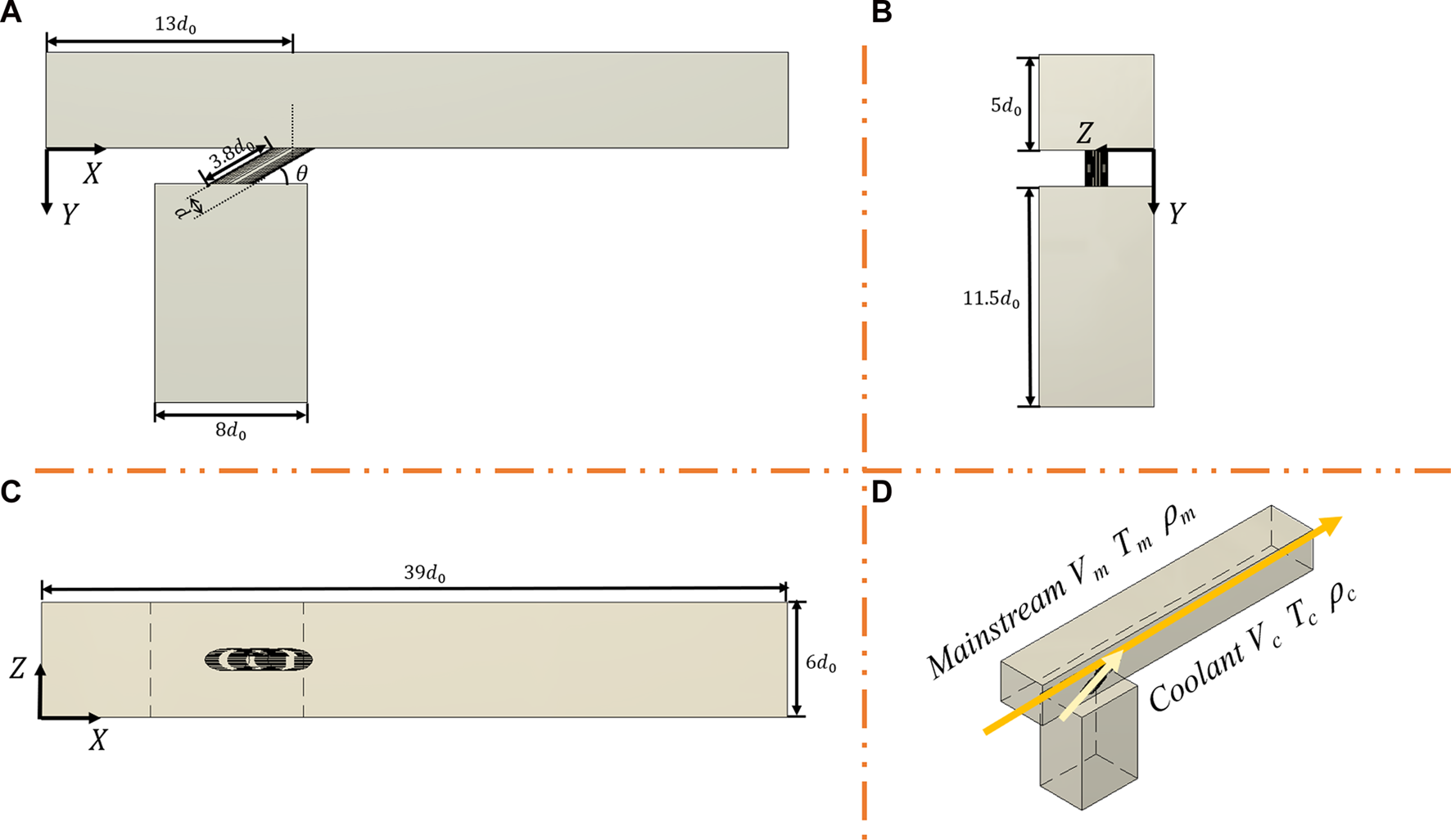
Schematic of the flat plate film-cooling configuration: (A) Front view; (B) Left view; (C) Top view; (D) Stereogram.
TABLE 1
| Cooling parameters | Values |
|---|---|
| Blowing Ratio, br | [0.5,1.0,1.5] |
| Film Cooling Diameter, d/(mm) | [10.5, 11.5, 12.5, 13.5, 14.5] |
| Coolant Inclination Angle, θ/(degree) | [15, 25, 35, 45, 55] |
| Density Ratio, dr | [1.1, 1.2, 1.3] |
| Mainstream Temperature, Tm/(K) | 313 |
| Mainstream Velocity, Vm/(m/s) | 20 |
Values of the film cooling parameters used in CFD.
Computational Assumptions and Variables
Ansys Fluent software is proven to have excellent performance in solving cooling problems (28-30). The problem is solved by applying steady-state solvers, which function by performing several iterations until the result converges. The standard to determine convergence is by comparing the continuity residual with 10−4 (27). If using a machine with 56 CPU to obtain the 225 datasets, it takes approximately 675 (225 hours. The mainstream and coolant inlet are assumed as velocity boundary conditions, and the mainstream outlet pressure is set to be 1 atm. Adiabatic and no-slip wall boundaries are applied for the mainstream and coolant chamber walls. Both flows are treated as superheated ideal gas, which follows the ideal gas law and is incompressible for low speed. The buoyancy effect is not assumed following Wang et al. (22, 27) and Yang et al. (26, 29). The Prandtl number of the turbulent is set to 0.667.
The dr and br are defined as shown in Eqs 1, 2. dr is defined as the temperature ratio at the mainstream versus the coolant jet. mean the mainstream jet gas density and coolant jet gas density, respectively. The subscripts “m” and “c” denotes mainstream and coolant, which remain the same for temperature T and velocity V which are defined later. Furthermore, the definition of br can be interpreted as the product of dr and the velocity ratio at the coolant jet and mainstream.
To avoid using a complicated high dimensional temperature matrix to represent the cooling efficiency, T* and are defined in Eqs 3, 4. T is the gauged temperature of the adiabatic and no-slip wall, with * denoting “dimensionless”, and short bar overhead “” labeling “fixed-cord-averaged.” To represent the wall temperature, the output is interpolated as a -dimensional matrix from 0 <z < 6d0, 13d0<x < 39d0.
Besides, the film cooling effectiveness at a single point, together with the fixed-cord-averaged and general film cooling effectiveness are derived according to dimensionless temperature T*, as shown below in Eqs 5–7.
Equation 8 defines the Mean Absolute Error (MAE), which is the index chosen to quantify the performance of a method. In the equations, m denotes the total sample size, ai is the training data gained by Reynolds-Averaged Navier-Stokes (RANS) model, and yi is the data acquired via the Large Eddy Simulation (LES) carried out by Wang et al. (31).
Turbulence Model Validation
Following other studies, the Fluent ® 18.0 software is applied to all cases (21, 31). A validation experiment is conducted on the downstream central line’s temperature and jet velocity distributions. This validation experiment aims to find the most suitable turbulence model for the following ANN and uncertainty quantification (UQ) analysis. The reference conditions are d = d0 = 12.5 mm, θ = 35°, dr = 1.2, and br = 1.0, which follows Wang et al.’s settings (27). The three candidate numerical methods are the SA model, the RNG k-ε model, the SST k-ω model, the Realizable k-ε model, and the experimental data from Ito (32, 33) and Sinha et al. (6) are used for comparison. The plot is shown in Figure 2, where x denotes the x-coordinate of the coolant jet outlet. The ratio x/d0 is set as an x-axis parameter in two plots to realize parallel comparison under different d0 selections. The coordinate interval researched is concentrated from 13d0< x < 39d0, 0< z < 6d0. The data located in the region where x < 13d0 is truncated because the constant mainstream temperature is assumed. In Figure 2A, the central-line film cooling effectiveness of the outer surface of the blade is computed via four numerical methods and two sets of experimental data. Figure 2B compares the four numerical models’ mean average values (MAE). The results indicate that the MAEs for the SA and Realizable k-ε models are larger than the SST k-ω and RNG k-ε models. Furthermore, the trend of the RNG k-ε model results matched better with the data obtained from the experiments. The MAEs for the SST k-ω and the RNG k-ε models are 0.0106 and 0.0117, respectively. In comparison, the MAE for the Realizable k-ε model and SA model are 0.0241 and 0.0228, respectively, which are almost twice as large as the RNG k-ε and the SST k-ω model. Therefore, the RNG k-ε model is utilized in this study.
FIGURE 2
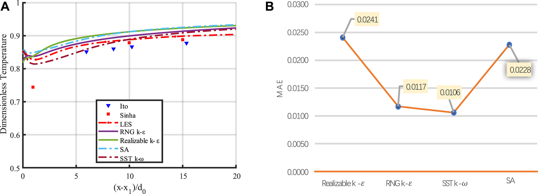
Comparison between model validation: (A) Dimensionless temperature comparison between models on center line results; (B) MAE comparison between models.
Grid Independence Study
In this study, the unstructured hybrid mesh is utilized. The y+ value for the near-wall cell is 1. Moreover, the grid stretch ratio is measured as 1.2 away from the solid wall. The grid cell number must be determined carefully since a massive number of grid cells raises the computational time meaninglessly, while too limited cell number conveys limited temperature distribution information and causes inaccuracy (34, 35). Therefore, the 2, 4.5, 6, and 7.5 million grid sizes are studied on the centerline of the flat plate model. The result is shown in Figure 3.
FIGURE 3
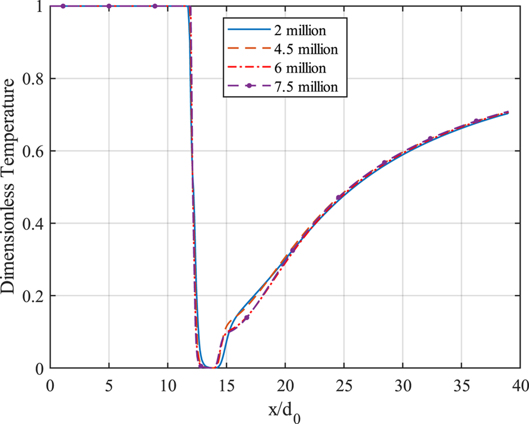
Centerline dimensionless temperature with 2, 4.5, 6, and 7.5 million grid cells.
When the location is right downstream of the coolant hole, the 2-million case obviously differs from 4.5, 6, and 7.5-million cases, whereas the difference narrows as the distance increases. The 7.5 million grid cell case has the most significant fluctuation among all, which implies that the 7.5-million case is the most sensitive to react. This paper sets the grid cell number at a 6-million grid size for analyzing training and validation CFD data. Figure 4 is the mesh schematic from three views: Axonometric, Front, and Top. It can be observed that a more accurate mesh resolution is located near the coolant hole.
FIGURE 4
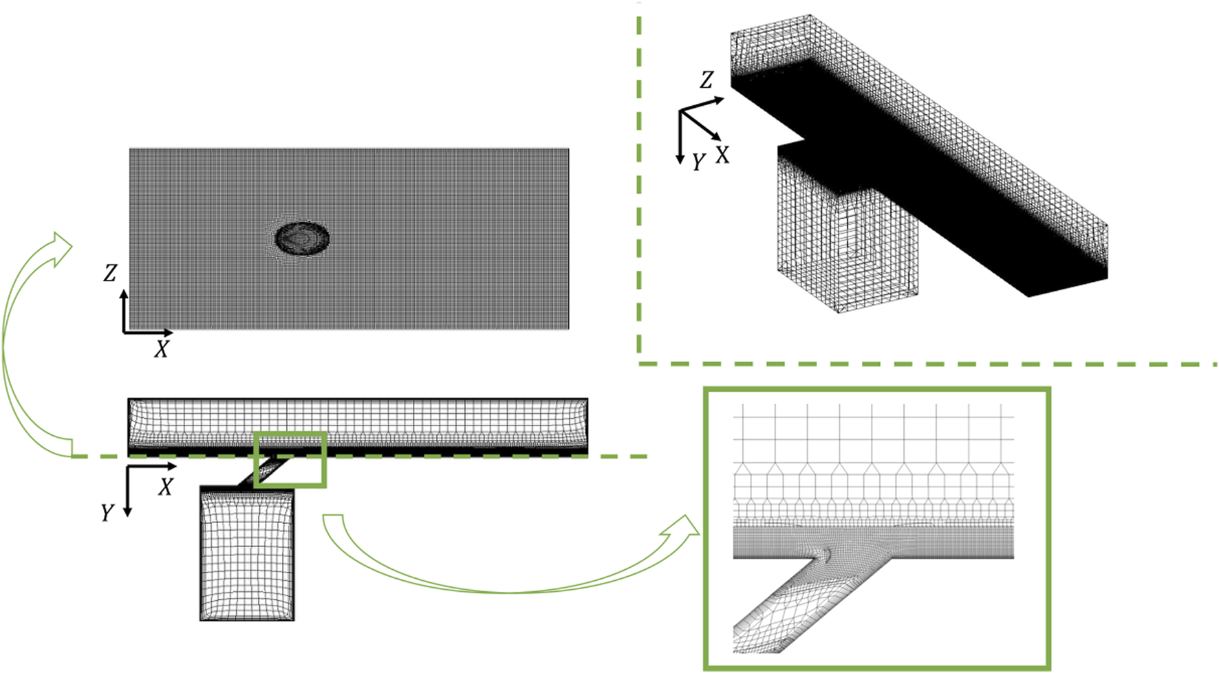
Mesh schematic with enlarged part.
Deep Learning Modeling and Validation
Data Preparation
Given the enormous computational amount of the CFD method, this paper adopts ANN to reduce the computational burden. The input is a matrix containing coolant tube diameter, coolant tube inclination angle, density ratio, and blowing ratio. The output is a -dimensional matrix, with each entry representing the grid’s temperature at the flat plate model’s external surface. Cooling effectiveness can thus be obtained from this output matrix by applying Eqs 3–7. The input data are normalized within (0, 1) before plugging into the input matrix. In Eq. 9, each parameter with the subscript “norm” stands for the corresponding parameter after normalization. The learning domain is set in the rectangular region, with x and z coordinates fulfilling 13d0<x < 39d0, 0<z < 6d0.
Structure of ANN
The ANN model is utilized to build the non-linear relationship between four flat plate configuration inputs, and the output temperature distribution matrix near the flat plate surface. The ANN model has seven layers in total, including one input layer, five hidden layers and one output layer. The first layer contains the four input parameters clarified above, and the information is propagated forward to the next layer through weighting, biasing, and activation (29). The activation of the first six layers is accomplished by applying the “Rectified Linear Unit” (ReLU) to intensify the non-linear regression before the output layer. A sigmoid function accomplishes the activation of the output layer.
Equation 10 shows the forward propagation process in the first six layers, where the weight matrix and bias matrix are denoted using W and b, respectively. The yh denotes the output of the 2nd, 3rd, 4th, 5th, and 6th layers. Equation 11 shows the forward propagation in the output layer. The yout stands for the output layer. In the output layer, final weighting and biasing are implemented. Then the result will be plugged into a sigmoid function to generate the predicted temperature distribution as the output value.
Batch normalization and dropout are implemented in the five hidden layers to enhance learning and avoid the neural network collapsing by big data. Mean square error (MSE) is deployed as a loss function to assess the difference between predicted temperature T and the CFD simulated value P, as shown in Eq. 12. The dropout is set to 0.1 in case of overfitting. The regression starts from 4 neurons and then multiplies until 256 neurons in the output layer. Figure 5 graphically illustrates the regression process. 45,176 parameters in total are yet to be defined.
FIGURE 5
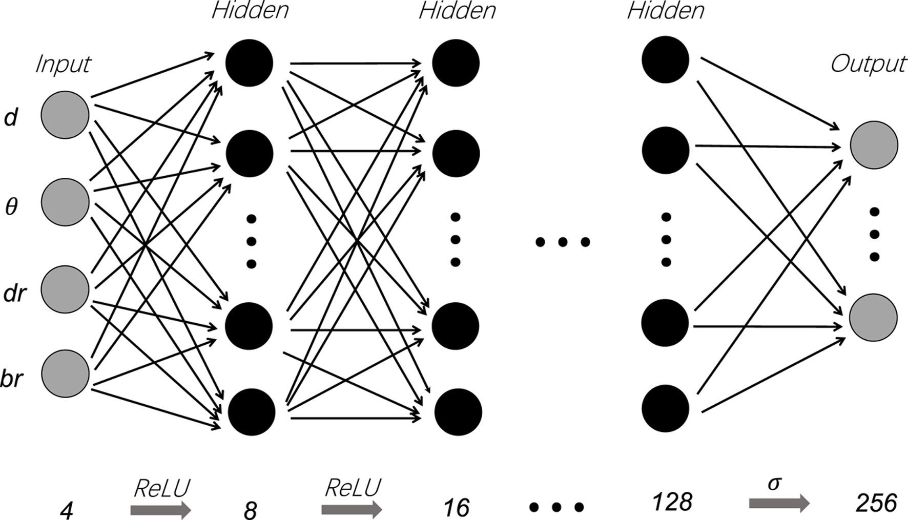
Structure of the 7-layer ANN model.
Training and Validation
In the training process, the learning rate is one of the most significant hyperparameters that needs to be determined when applying ANN (36, 37). In this study, the learning rate is set to 0.01, and it is reset to 10% of its former value after every 1,000 epochs to keep convergence. The MSE is used to be the error index to evaluate whether the convergence of the model is accomplished. Figure 6 shows that as the number of epochs increases, the MSE value converges. There is a noticeable fluctuation before the epoch reaches around 500. However, with the continuous growth of epochs, the value of MSE and the fluctuation keep falling.
FIGURE 6
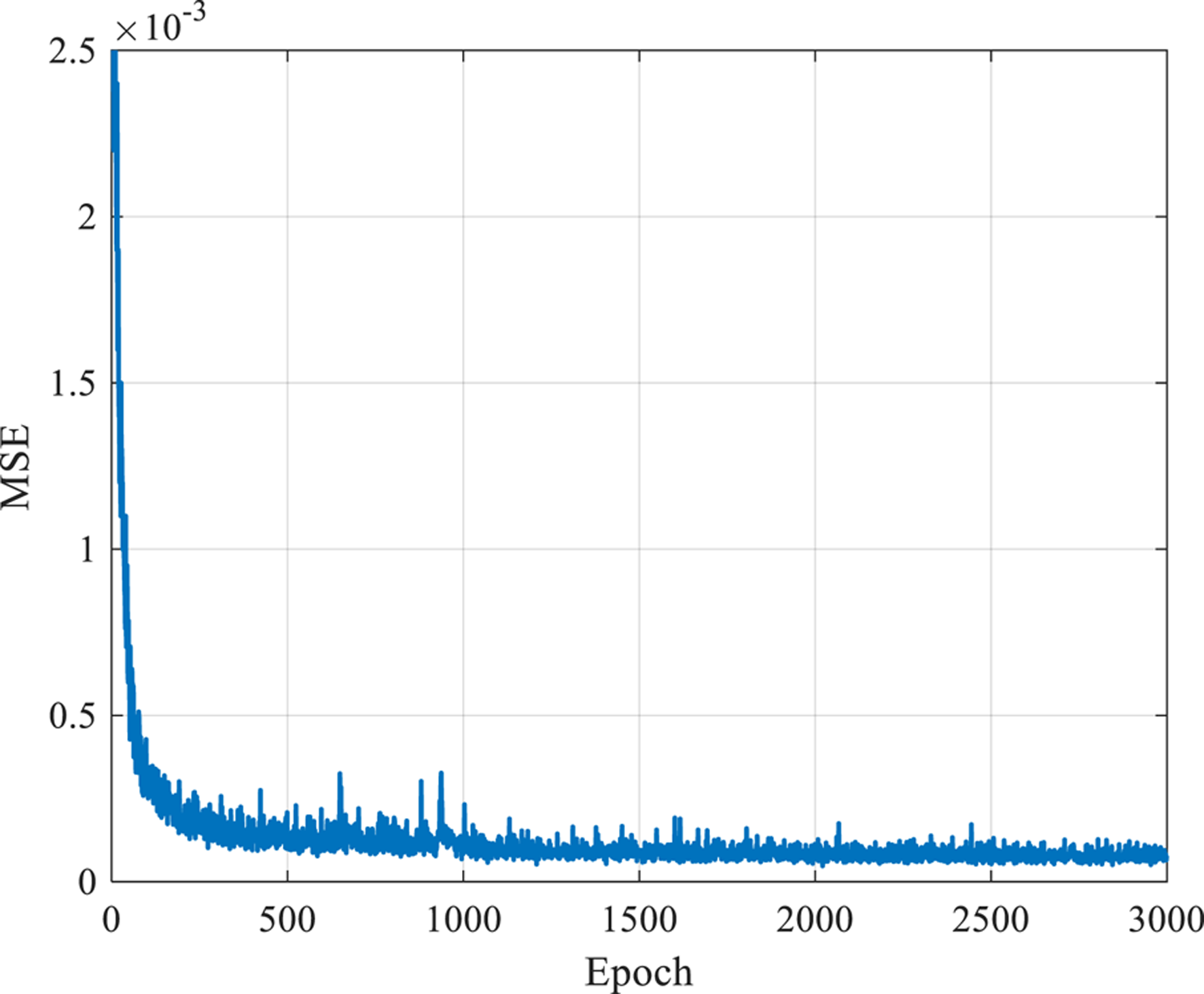
Loss of the ANN model.
According to the result, the 0.01 learning rate and reduction to 10% of its last value every 1,000 epochs is a good choice. Quoted error (QE) is proposed in Eq. 13 to measure the ANN model’s absolute error. QE also serves as an index to help find the optimal hyperparameter settings. In the expression of QE, T is the temperature derived from CFD simulation, and P is the predicted temperature result at the final layer of the ANN. is a fixed number 0, and the upper bound of . The result is scaled to a hundred percent of the corresponding QE value.
The ANN model uses QE to find the optimized hyperparameter settings containing splitting ratio, dropout, and batch size. The splitting ratio is acquired by dividing the amount of validation dataset by the whole dataset. A higher splitting ratio means a relatively lower portion of data is utilized in the training process. Thus, a balance in training and validation must be determined to achieve better prediction efficiency and accuracy. An experiment aiming at finding the optimal splitting ratio is conducted, and the result is shown in Figure 7A. The QE value of the case with splitting ratio = 0.2 is the highest compared with the situations whose splitting ratios are 0.1 and 0.3, which indicates that there is no simple proportional relationship between the magnitude of the error and the magnitude of splitting ratio. Besides, it is found that the QE value of the validation dataset is always higher than the training dataset by the ANN algorithm, regardless of which splitting ratio is chosen. Results show that a splitting ratio of 0.3 is believed to be the best among the three splitting ratios researched.
FIGURE 7
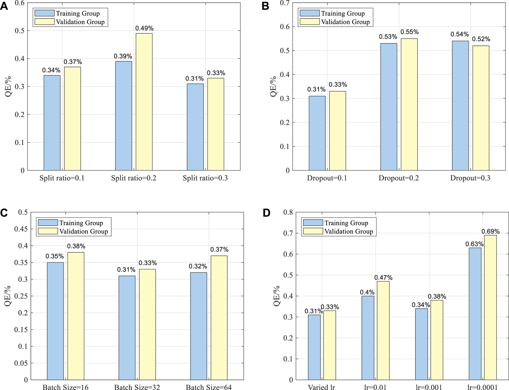
QE values under different hyperparameters setups: (A) Splitting ratio; (B) Dropout; (C) Batch size; (D) Learning rate.
Similar experiments are designed for dropout and batch size. Figure 7B is the result of finding the ideal dropout. There is an apparent disparity between the case where the dropout is 0.1 compared to cases with 0.2 and 0.3 dropouts. The QE for the training dataset with 0.1 dropout is 0.31%, and the QE for the validation dataset with 0.1 dropouts is 0.33%. The QEs for the other two cases vary from 0.52% to 0.55%, which are much larger than those with a dropout of 0.1. This proves that the case with a dropout of 0.1 has the least error between the predicted temperature and the simulated value.
For Batch size, three different batch sizes are studied, and Figure 7C plots the result. The QE values of three different batch sizes are all located at [0.31%,0.38%], which implies that the batch size does not serve as a significant parameter with a considerable influence on the output in the ANN model. In the case with 32 batch size, the MSEs for the validation and training datasets are 0.33% and 0.31%, respectively. Therefore, the optimal batch size of 32 is chosen. For learning rate, as shown in Figure 7D, it is easily found that the varied learning rate could provide the best performance over the fixed learning rate such as 0.01, 0.001, and 0.0001. In all, the optimal hyperparameters are: dropout = 0.1, batch size = 32, splitting ratio = 0.3, and a varied learning rate.
Moreover, the structure of the ANN has been investigated to obtain the best performance. With these optimal parameters, the number of layers is determined to be 7 and the modes are determined according to the symmetry aiming for best training results. The information of different layers and nodes selection is shown in Table 2 below. We chose 2, 3, 4, 7, and 9 layers because under these cases, the nodes arrangements are symmetric from 4 nodes to 256 nodes. In the experiment, we find that when the layer number comes to 7, the quoted error value (QE) reaches its minimum. However, we find that the quoted value of the 9-layer case increases, which is because too much layer increases the number of parameters and the iteration error. In the process of training, it is also reasonable in practice that some parameters are lost. After comparison, we find that the QE value of the 7-layer case is quite acceptable, so we consider 7 layers as the best layer number choice.
TABLE 2
| Number of layers | Nodes details | QE for training group (%) | QE for validation group (%) |
|---|---|---|---|
| 2 | 4-256 | 0.91 | 0.96 |
| 3 | 4-128-256 | 0.35 | 0.40 |
| 4 | 4-16-64-256 | 0.32 | 0.36 |
| 7 | 4-8-16-32-64-128-256 | 0.31 | 0.33 |
| 9 | 4-8-16-16-32-64-64-128-256 | 0.34 | 0.45 |
Layers and nodes information and corresponding QE values.
To further visualize the prediction accuracy using the designed ANN model, the fixed-cord-averaged film cooling effectiveness achieved by the ANN and CFD method simulation are compared for training and validation datasets. Six cases with diverse input parameter sets containing θ, d, dr, and br are randomly selected. The fixed-cord-averaged film cooling effectiveness on the upper surface of the turbine blade under six different cases are shown in Figure 8. All the six plots in Figure 8 are about the fixed-cord-averaged cooling effectiveness results. The blue dotted lines in the plots represent the CFD cooling results, while the red line indicates the ANN results.
FIGURE 8
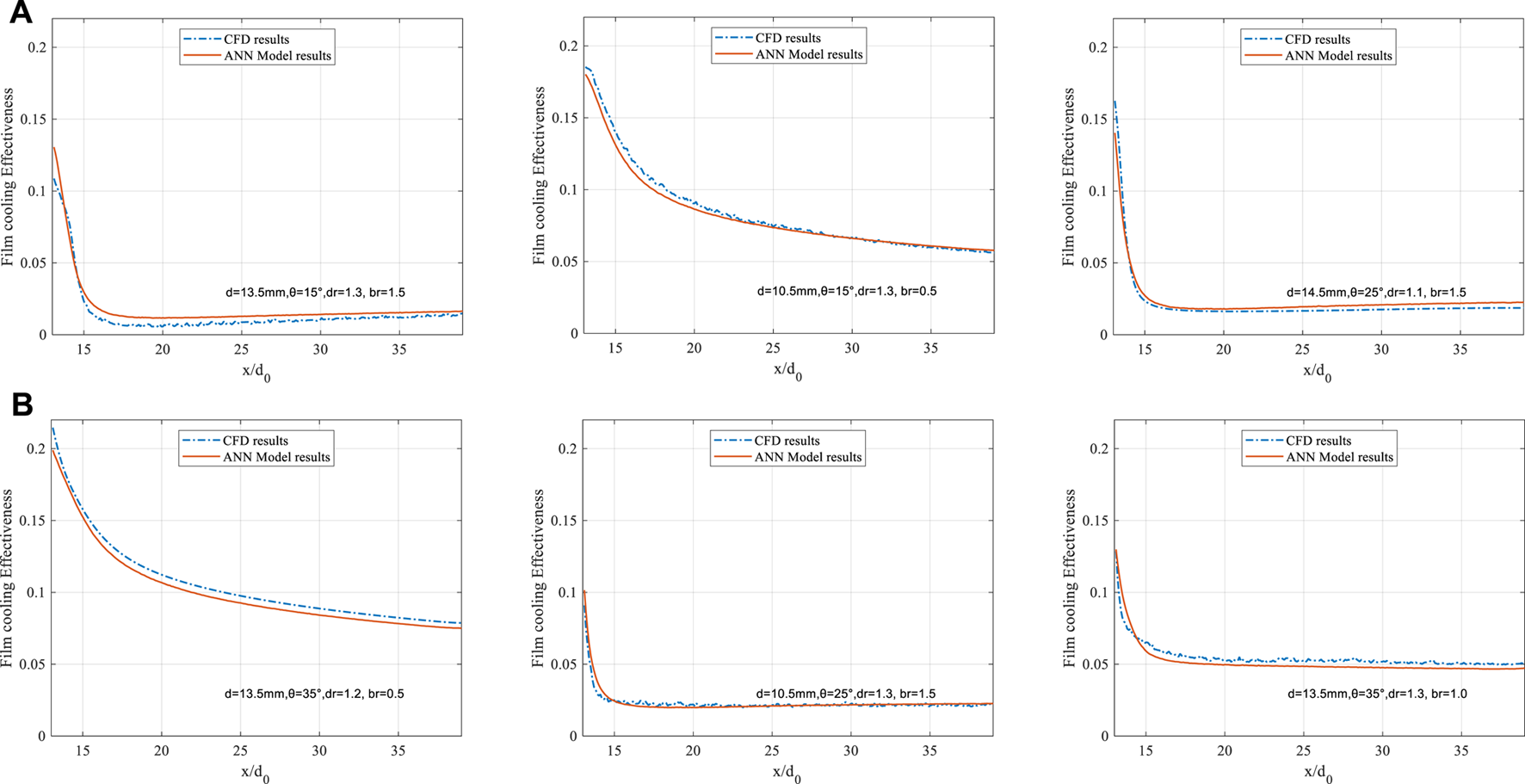
Fixed-cord-averaged cooling effectiveness results comparison by the ANN and CFD model; (A) Training datasets; (B) Validation datasets.
Figure 8A is for training datasets, and Figure 8B is for validation datasets. The result shows that the temperatures predicted using the ANN model for the training and validation datasets almost overlap with the temperatures obtained from CDF simulation. For example, in the case where d = 10.5 mm, θ =15, dr = 0.3, br = 0.5, the fixed-cord-averaged cooling effectiveness derived by CFD is 0.108 when x/d0 is positive zero, compared with the result derived by the ANN model of 0.130. While x/d0 increases up to 15, the two curves almost overlap, and the error is negligible. After x/d0 goes beyond 15, the error expands to its maximum value of 4.28%, where x/d0 equals 17.4. Then, as x/d0 keeps increasing, the error minimizes continuously. At the back end of the research region, the error is close to zero again. For fixed-cord-averaged film cooling effectiveness, the QE for training datasets is 0.29%, while for the validation dataset it is 0.32%. Conclusion can be drawn that even though fluctuation still occurs inevitably, the regression performance of the ANN model in fixed-cord-averaged film cooling effectiveness is delighted under all randomly selected cases.
Besides the fixed-cord-averaged cooling effectiveness, the general cooling effectiveness is also studied to enhance the above conclusion. Figure 9 compares the overall film cooling effectiveness from CFD and ANN methods downstream the coolant hole. The relationship between general film cooling effectiveness and computation numbers is plotted in Figure 9. 225 () cases of 0.3 splitting ratio are included, which means that Figure 9A includes the 156 training data, Figure 9B includes the 69 validation data. And they are ranked according to the magnitude of their general film cooling effectiveness to exhibit the results in a visual-friendly way. We labeled each data point using Computation No. from 1 to 156 and from 1 to 69 as shown on the horizontal axis. So, two lines are both discrete lines. Even though it is inevitable for the ANN and CFD results to have differences because the ANN’s training data are derived from CFD. The results show that the general film cooling effectiveness derived from the ANN model is accurate enough for both training and validation data, regardless of the computation number. For general film cooling effectiveness, the QE for training datasets is 0.35%, while for the validation dataset, it is 0.30%.
FIGURE 9
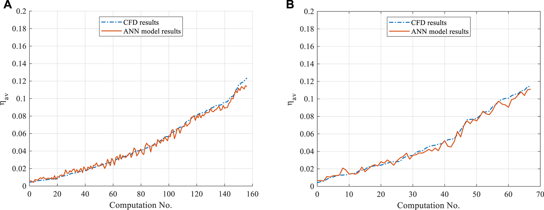
General results comparison by the ANN and CFD model; (A) Training datasets; (B) Validation datasets.
Uncertainty Analysis
Monte Carlo Simulation and Sample Size
As the designing and manufacturing processes are deterministic, the variety of structures is usually not considered. For products with simple designs, the function could be achieved. However, the performance of sophisticated appliances such as gas turbines could vary significantly due to the uncertain deviation of their parameters. The best way to analyze and reduce unexpected uncertainty is to conduct an uncertainty quantification analysis of all related parameters (38, 39). In this paper, the parameters studied are d, θ, dr, and br.
Monte Carlo (MC) simulation is an extensively utilized technique to quantify the engineering field’s uncertainty among various kinds of uncertainty quantification methods (40). MC simulation conducts statistical analysis to sample datasets obtained by repeated random sampling (41). MC simulation shows excellent advantage in mathematics and engineering due to its concise methodology, broad application domain, and various software choices (38). The mean and standard deviation of the mean squared pure error (MSPE), namely are studied instead to impair its harmful effect. The random samples are generated in the following way: Firstly, a sample vector is formed from the normalized training dataset, which is = (d, θ, dr, br), and each entity is normalized with a value ranging from 0 to 1 according to Eq. 9. Secondly, enough sample vectors are generated in the same way and are arranged to form a distribution X for the following MC simulation. The sample size is defined as the number of sample vectors in each distribution. Therefore, parallel experiments are conducted, and the MSPE is proposed to quantify how well the MC simulation behaves. The mean and the standard of MSPE are defined in Eq. 14. The experiment results are shown in Figure 10. It can be observed that even though the almost remain at a steady level, when the sample size is below 10,000, the fluctuation of both are very large, which represents that a sample size smaller than 10,000 is not suitable for MC simulation. As the sample size increases, however, the undulations of both the mean and the standard deviation narrow and remain stable continuously. Therefore, 10,000 is chosen as the optimal sample size for this research.
FIGURE 10
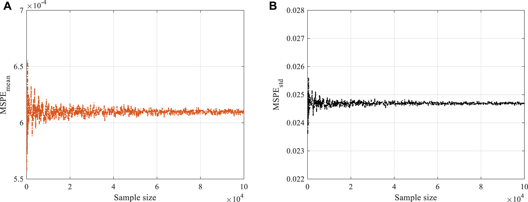
MSPE values for MC for diverse sample size: (A) Mean of MSPE (B) Standard deviation of MSPE.
Sensitivity Analysis by Sobol Method
After the parameter distribution is settled, the Sobol method is utilized to investigate how the sensitivity of br, d, θ influences the film cooling effectiveness under three different values of dr. The Sobol method shows excellent performance in the sensitivity analysis (42, 43). The sample vector x is firstly transferred into the uncertainty input vector {X1, X2, X3}, where X1, X2, and X3 denote coolant hole diameter, inclination angle, and density ratio, respectively. A functional mapping Y = f(X) is constructed to represent the relation between X and Y, where Y is the general film cooling effectiveness, defined in Eq. 7.
Sobol indices are defined in Eq. 15, where Si and STi are the first and total-effect variance-based Sobol indices, respectively. The Sobol index is used to quantify the sensitivity of a parameter. The larger the Sobol index is, the more significant impact its corresponding parameter has. Xi is the input parameter among the uncertainty input set {X1, X2, X3}, X∼i denotes the set of all the input variables but Xi. By applying uncertainty deviation to each of the four-parameter sets, Y is affected to vary accordingly. Hence, the variances of Y under diverse scenarios are defined in Eq. 16.
In addition to Si and STi, the temperature distribution near the blade also needs attention. If the blade surface is well covered by the cooling jet, its life span and reliability could be extended and increased heavily. To set up computation, the Probability Distribution Function (PDF) is introduced to represent the distribution of cooling effectiveness of every grid point on the flat surface of the turbine blade. The PDF are defined in Eq. 17. Where y denotes the general film cooling effectiveness predicted by the ANN model, μ and σ is the mean value and standard deviation of the y.
Test Case Definition and Turbulence Model Selection
By applying the uncertainty Sobol method to represent the three geometric parameters at blowing ratios of [0.5, 1.0, 1.5], the results of experiments are plotted in Figures 11A–C.
FIGURE 11
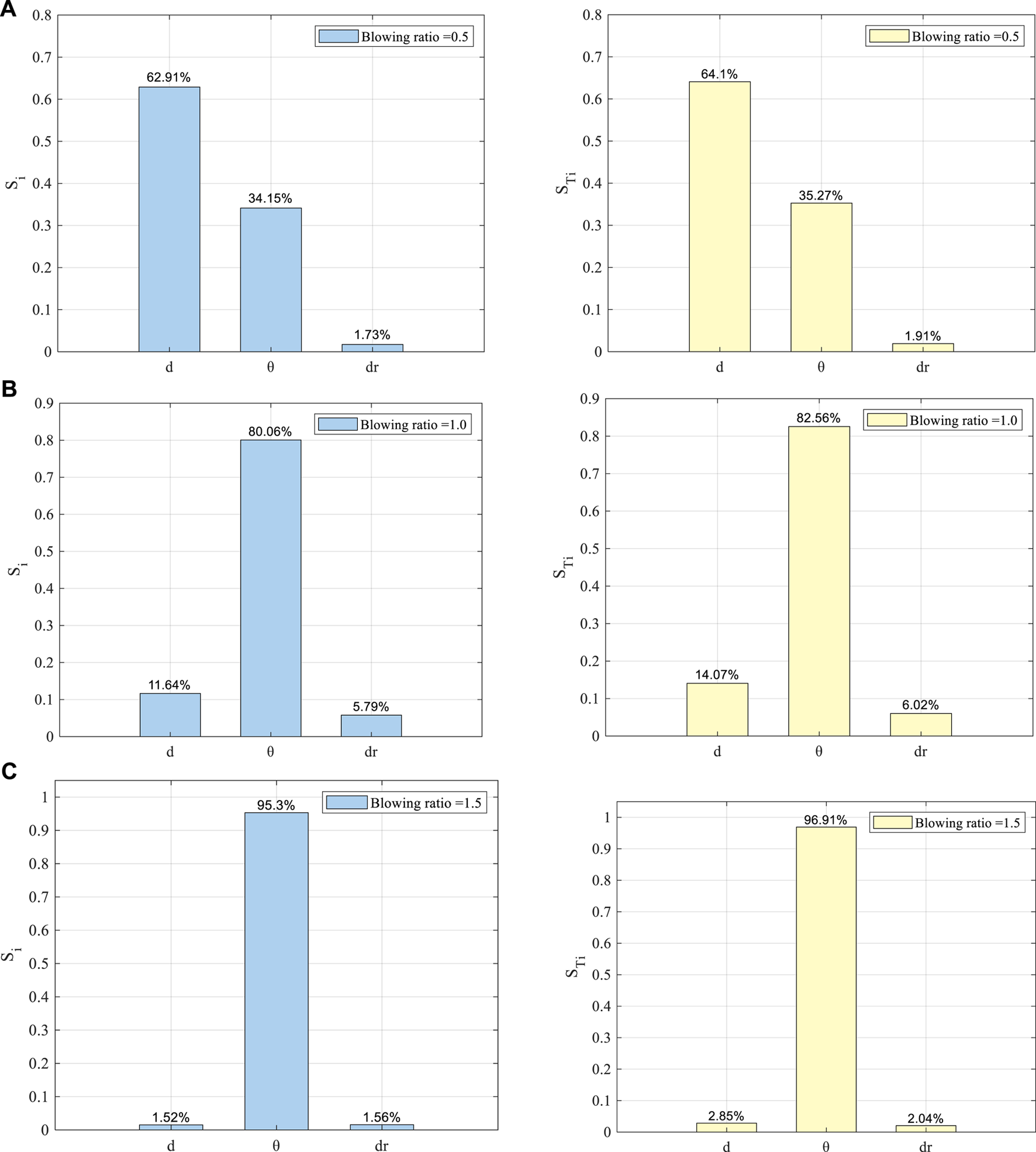
Sodol Indices for , , dr at (A)br = 0.5; (B)br = 1.0; (C)br = 1.5.
Figure 11A shows that at the low blowing ratio, the coolant hole diameter d has the largest value for both the Si and . It means that among the three geometric parameters, the deviation of coolant hole diameter has the largest uncertainty influence on the global film cooling effectiveness at a low blowing ratio. Followed by the hole diameter is the coolant jet inclination angle. Regardless of or , the uncertainty Sobol indices are both around 35%. The deviation of the density ratio is the weakest of all three parameters, the Sobol indices of which are less than 2%. In all, when the blowing ratio is set to 0.5, the trends of Si and STi for d and dr show high similarity. d is the dominant index which composites nearly 64%, yields around 35%, and dr has the most minimal effect on the uncertainty result.
For the medium-blowing ratio of 1.0, the order of the impact of the three geometric parameters changes utterly. Figure 11B shows that the difference between the and the is tiny. Still, the affects the result far more than the other two parameters. The and of θ both exceed 80%, which are approximately eight and fifteen times more than those of d and dr. It can be concluded that when the br is 1.0, the uncertain deviation of has the most significant impact on the general film cooling effectiveness.
Figure 11C indicates that for a large blowing ratio of 1.5, the corresponding result can be interpreted as a magnified one of a blowing ratio of 1.0. The coolant hole inclination angle is still the primary parameter, but its Sobol index is furthermore prominent than the medium-blowing ratio case. This time, the first-order and overall Sobol indices for θ outstrip 95%. Compared with the Sobol indices under the medium blowing ratio br, the hole diameter d and density ratio dr, which are all less than 3%, show negligible influence on the general cooling effectiveness. Moreover, it is found that when the blowing ratio increases, the Si and STi for all parameters increase accordingly.
In the gas turbine application, in a low blowing ratio case, both the coolant hole diameter and inclination angle significantly impact cooling effectiveness. However, the uncertain deviation of coolant hole diameter has a more significant effect. As for a high blowing ratio, usually more than 1.5, the coolant hole inclination angle needs special attention. In medium and high blowing ratio cases, the coolant inclination angle dominates the results, and its dominant effect increases as the blowing ratio increases, in all three cases. The trends of the first-order and the total-effect index are very similar. Thus, the same conclusion can be drawn.
Figure 12 shows the flow field of the flat plane. Since there are up to 225 cases in total, a reference case for the flow field example is defined with the following parameters: d = 14.0 mm, θ =, dr = 1.2, br = 0.5. Figure 12A is the top view. It can be found that the flow field is highly symmetric on the top surface, and the green region is the widest temperature region, which occupies more than half the length of the region downstream of the confluence on the centerline. Moreover, the lateral diffusion is not evident since the width of the coolant stream keeps nearly equal to the hole diameter. Figure 12B is the front view of the flow field. It is detectable that right downstream the coolant hole, a reverse vortex pair is generated that drives the coolant jet away from the blade. A portion of the coolant on the top blends into the mainstream. The flow field shows that as the two jets move forward, the convergence of the two streams becomes more pronounced. Thus it is true that the coolant jet performs well only at a limited distance downstream of the confluence point. The reference case has a blowing ratio of less than 1, which means that the mainstream moves faster than the coolant jet, so Figure 12C indicates in the cross-section view that the general effect of gas motion is moving from the coolant jet to the hot mainstream. This leads to the coolant jet’s diffusion and thus significantly impairs the cooling effectiveness. While in the cross-section view, we can also find that the coolant jet, which stays near the surface of the turbine blade, is rotating in a closed loop, that ensures that coolant is not lifted away from the blade, and achieves better cooling effectiveness at the surface layer of the blades.
FIGURE 12
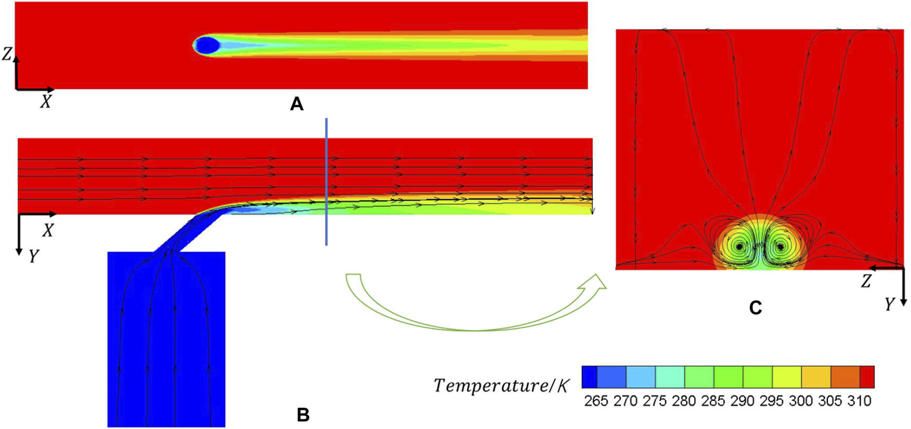
Details of flow fields under different views: (A) X-Z; (B) X-Y; (C) Y-Z.
During the experiment and analysis, it is found that under the small blowing ratio case of br = 0.5, the coolant hole diameter d has more impact sensitivity on the general film cooling effectiveness, compared with the coolant inclination angle. However, under a larger blowing ratio of 1.0, the coolant inclination angle has more effect than hole diameter. To further explain the flow physics that account for this result, the flow field of the cases under low and high blowing ratios, including d = 10.5 mm and 11.5 mm, coolant inclination angles of 20 and 30, and in both x-z and y-z direction are compared and analyzed. From a top view, by comparing Figures 13A,B and Figures 13A,C, we find that the low-temperature region at the center of the coolant hole expands to a larger degree under the influence of diameter change. This discovery implies that under a small blowing ratio of br = 0.5, the change in cooling effectiveness due to diameter change is larger than the change due to inclination angle. As for the case where the blowing ratio is as large as br = 1.0, Figures 13D,E and Figures 13D,F shows that the influence of the inclination angle is larger than the influence of the diameter, because the coolant flow in (F) shrinks dramatically, while the ones in (D) and (E) are similar to each other. Figure 14 shows the cross-section view of the same 6 cases in Figure 13. When the blowing ratio is low, the difference of width of the CVP between Figures 14A,B is larger than the difference between Figure 14A,C; whereas, under a large blowing ratio, the coolant CVP is lifted to a larger degree in the case of increasing the angle instead of increasing thecoolant hole diameter. As shown in Figure 14F, the height of the CVP center climbs higher under the influence of the inclination angle compared with Figure 14E. Furthermore, the CVP is rotating upward, which results in the additional lifting of the coolant flow at the location of x/d = 19. This impairs the cooling effectiveness as well.
FIGURE 13
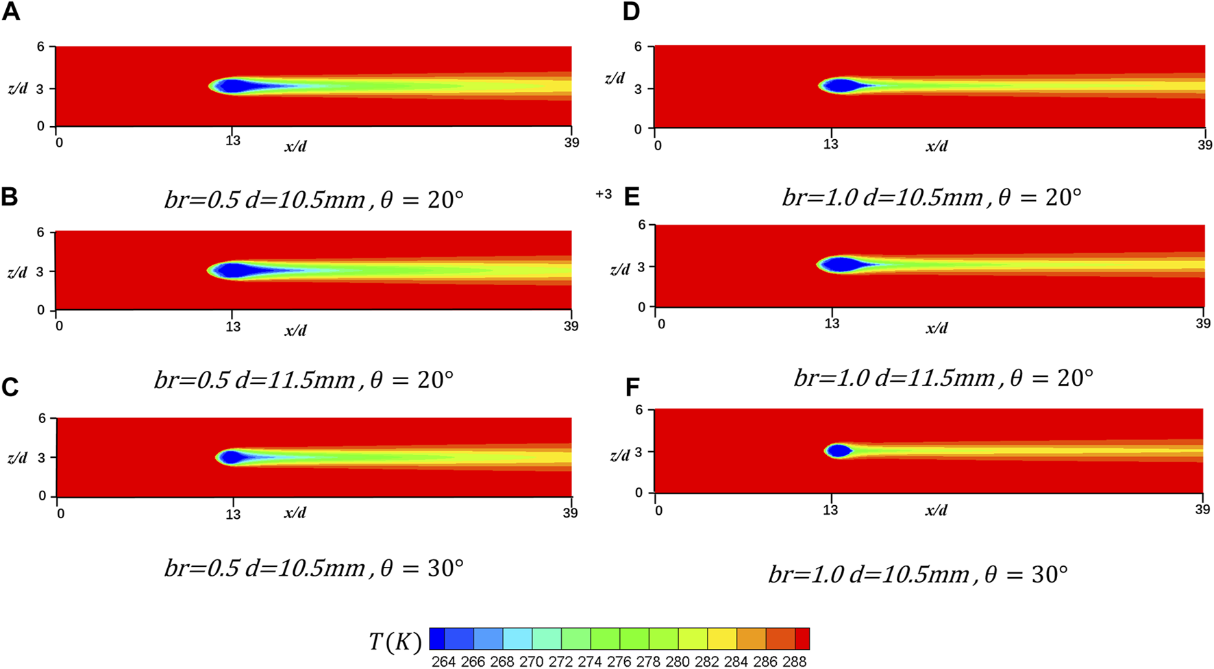
Comparison of the top-view flow behavior at y/d = 0 in x-z plane. (A)br = 0.5, d = 10.5 mm, θ = 20°; (B)br = 0.5, d = 11.5 mm, θ = 20°; (C)br = 0.5, d = 10.5 mm, θ = 30°; (D)br = 1.0, d = 10.5 mm, θ = 20°; (E)br = 1.0, d = 11.5 mm, θ = 20°; (F)br = 1.0, d = 10.5 mm, θ = 30°.
FIGURE 14
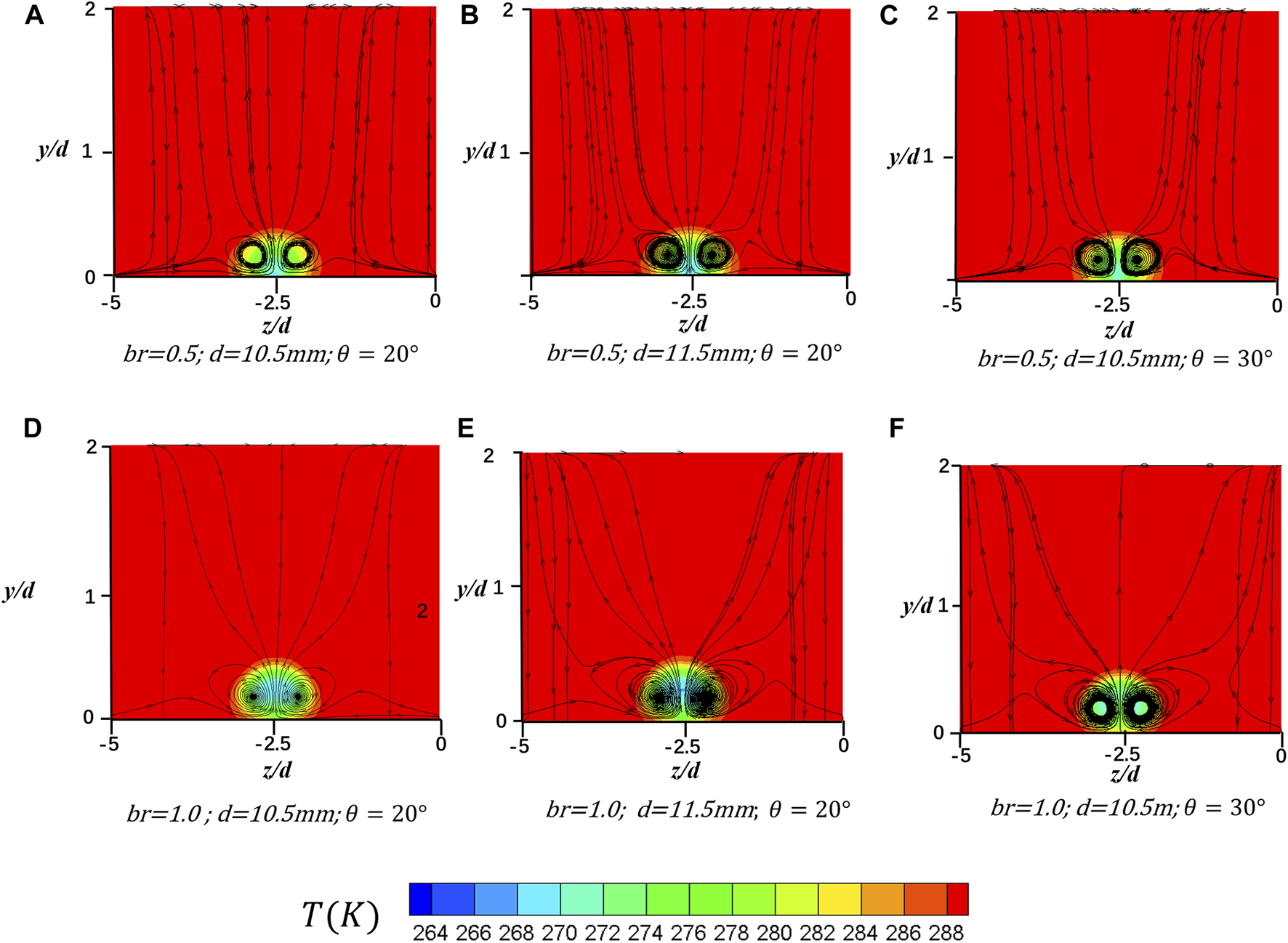
Comparison of the side-view flow behavior at x/d = 16 in y-z plane. (A)br = 0.5, d = 10.5 mm, θ = 20°; (B)br = 0.5, d = 11.5 mm, θ = 20°; (C)br = 0.5, d = 10.5 mm, θ = 30°; (D)br = 1.0, d = 10.5 mm, θ = 20°; (E)br = 1.0, d = 11.5 mm, θ = 20°; (F)br = 1.0, d = 10.5 mm, θ = 30°.
In addition to utilizing Sobol indices on behalf of the sensitivity, the control variate method is deployed to further research the individual effect of the three independent geometric parameters on the general effectiveness of cooling under three different blowing ratios in terms of the probability distribution(44). The reference values for d, θ, and dr are 12.5 mm, 35°, and 1.2 respectively. While varying one of the three, the others are set as the value in the reference case to achieve uniformity. Figure 15 shows the probability distribution of general cooling effectiveness at different blowing ratios. The four subplots study the three single-parameter effects and the combined effect.
FIGURE 15
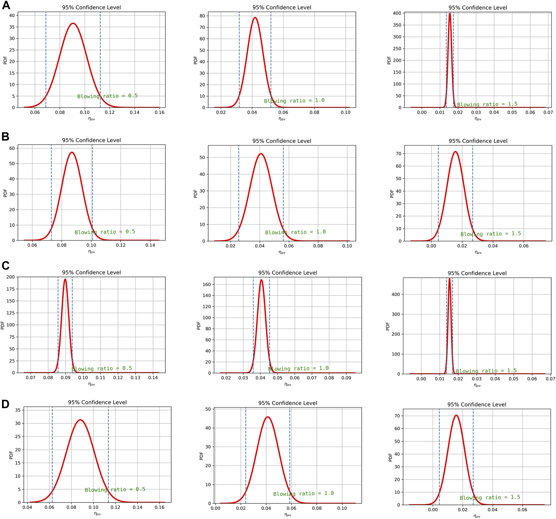
PDF distribution of general film cooling effectiveness at three blowing ratios: (A)d; (B)θ; (C)dr; (D) Combined effect.
As shown in Figure 15A, the PDF distribution of the coolant hole diameter is studied. When the blowing ratio is 0.5, the 95% confidence interval due to hole diameter is [0.070, 0.113]. However, those for blowing ratios of 1.0 and 1.5 are [0.030, 0.049] and [0.014, 0.017], respectively. The corresponding interval length for the three blowing ratios are 0.043, 0.019, and 0.003, respectively. The result shows that as br is increasing, the 95% confidence interval due to hole diameter narrows rapidly, almost halving each time, and the mean of general cooling effectiveness decreases continuously, indicating that the uncertainty caused by hole diameter decreases.
For the hole inclination angle, as shown in Figure 15B, when the br increases, the uncertainty effect maintains a high level due to the hole inclination angle. The confidence intervals remain wide for all low, medium, and high blowing ratios. This is different from the case for hole diameter. With the increase of br, the range of variation of general film cooling effectiveness of inclination angle decreases from 0.030, 0.029 to 0.023 after simple calculation. It can be concluded that with the increasing of the blowing ratio, the uncertainty caused by the inclination angle θ reduces, but with a lower decreasing speed than the hole diameter.
Figure 15C shows that the magnitude of the length of the confidence interval of the density ratio is the smallest among all parameters. However, the PDF value of the density ratio is the highest, the minimum value of which still exceeds 160 in the case of the br = 1.0.
The uncertainty of the combined effect decreases as br rises, and the combined effect is more prominent than all three single effects. In Figure 15D, for example, the 95% confidence intervals are [0.062, 0.112], [0.023, 0.058], [0.004, 0.027], and the interval lengths are 0.060, 0.035, and 0.023, respectively. Compared with the single effect caused by the inclination angle θ, the interval length of the combination becomes wider.
Conclusion
This study aims to improve the gas turbine performance by strengthening the film cooling effectiveness, especially by focusing on the uncertainty of the three significant parameters, including single hole diameter, density ratio, and inclination angle, on the film cooling effectiveness under low, medium, and high blowing ratios. The uncertainty analysis was conducted using a deep-learning-based ANN model and uncertainty quantification method. Firstly, all related indices and research regions are defined at the beginning. Due to its best performance, the six-million grid size and the RNG k-ε model are chosen for the turbulence model. Secondly, a high-performance ANN model is delicately constructed for training and to seek the non-linear correlation between the parameter input and the cooling effectiveness output. CFD provides training and validation datasets. Finally, the sensitivity of three parameters is quantified, and uncertainty quantification is conducted to quantify the single and combined effect of the uncertainty of these three parameters on the general cooling effectiveness. The following conclusions are drawn.
1. After careful hyperparameter selection and training, the ANN model built in this study shows excellent performance in predicting the general and fixed-cord-averaged film cooling effectiveness according to input parameters compared with the data simulated by the CFD method. The QE value for fixed-cord-averaged film cooling effectiveness in training and validation datasets are 0.29% and 0.32%. The QE value for general film cooling effectiveness in training and validation datasets are 0.35% and 0.30%.
2. The Sobol method based on MC simulation shows that at a small blowing ratio, the coolant tube’s diameter and inclination angle are two main factors to the cooling effectiveness, and the former has a more dominant effect. At medium and large blowing ratios, the inclination angle is the only leading factor to the film cooling effectiveness. Furthermore, the maximum effect of the inclination angle increases as the blowing ratio grows.
3. Uncertainty quantification reveals that the uncertainty of hole diameter, inclination angle, and density ratio all decrease as the blowing ratio rises. Moreover, the combined effect shows a higher impact on the general cooling effectiveness than any single effect. Within three parameters, the variation of the uncertainty interval of the hole diameter at three blowing ratios is the most obvious. Furthermore, the inclination angle θ has the most extensive uncertain influence on the general film cooling effectiveness among the three single parameters
Statements
Data availability statement
The data that support the findings of this study are available from the corresponding author upon reasonable request.
Author contributions
YW: Conceptualization, data curation, formal analysis, investigation, methodology, resources, software, validation, and writing–original draft. XQ: Data curation, formal analysis, investigation, resources, visualization, and writing—original draft. SQ: Investigation, resources, visualization, and writing—original draft. YS: Data curation, formal analysis, methodology, visualization, and writing—original draft. WW: Resources, software, and validation. JC: Conceptualization, formal analysis, funding acquisition, investigation, project administration, software, supervision, visualization, writing—review and editing.
Funding
This study was supported in part by State Key Laboratory for Aerodynamics, the Zhejiang University/University of Illinois at Urbana-Champaign Institute and National Natural Science Foundation of China (Grant No. 52106060 and 92152202). It was led by Supervisor JC.
Conflict of interest
The authors declare that the research was conducted in the absence of any commercial or financial relationships that could be construed as a potential conflict of interest.
Publisher’s note
All claims expressed in this article are solely those of the authors and do not necessarily represent those of their affiliated organizations, or those of the publisher, the editors and the reviewers. Any product that may be evaluated in this article, or claim that may be made by its manufacturer, is not guaranteed or endorsed by the publisher.
Nomenclature
- d
film cooling diameter
- d0
standard Value of d
- θ
coolant tube inclination angle
- br
coolant-to-mainstream blowing ratio
- dr
coolant-to-mainstream density ratio
- ρc
density of coolant jet
- ρm
density of mainstream jet
- Vc
velocity of coolant jet
- Vm
velocity of mainstream jet
- T
gauged temperature
- Tc
temperature of coolant jet
- Tm
temperature of mainstream jet
- T*
dimensionless temperature
fixed-cord-averaged T*
- η
film cooling effectiveness
fixed-cord-averaged η
- ηav
general film cooling effectiveness
- MSE
mean square error
- QE
quoted error
- Si
first-order sensitive index
- STi
total-effect sensitive index
- MSPE
mean squared pure error
standard deviation of MSPE
mean of the MSPE
- μ
mean
- σ
standard deviation
- PDF
probability distribution function
References
1.
Thamir KI Ahmed NA . Improvement of gas turbine performance based on inlet air cooling systems: A technical review. Int J Phys Sci (2011) 6(4):620–7. 10.5897/IJPS10.563
2.
Garg VK Gaugler RE . Effect of coolant temperature and mass flow on film cooling of turbine blades. Int J Heat mass transfer (1997) 40(2):435–45. 10.1016/0017-9310(96)00040-3
3.
Han JC Ekkad S . Recent development in turbine blade film cooling. Int J Rotating Machinery (2001) 7(1):21–40. 10.1155/s1023621x01000033
4.
Ekkad S Han J‐C . A Review of Hole Geometry and Coolant Density Effect on Film Cooling. In: Proceedings of the ASME 2013 Heat Transfer Summer Conference; 2013 Jul 14–19.: Minneapolis, MN (2013).
5.
Yang X Zhang K Wu J Lei J Su P Fang Y . Numerical analysis of vane endwall film cooling and heat transfer with different mainstream turbulence intensities and blowing ratios. Int J Therm Sci (2022) 175:107482. 10.1016/j.ijthermalsci.2022.107482
6.
Sinha AK Bogard DG Crawford ME . Film-cooling effectiveness downstream of a single row of holes with variable density ratio. J Turbomach (1991) 113. 10.1115/1.2927894
7.
Cao N Li X Wu Z Luo X . Effect of film hole geometry and blowing ratio on film cooling performance. Appl Therm Eng (2020) 165:114578. 10.1016/j.applthermaleng.2019.114578
8.
Gritsch M Schulz A Wittig S . Adiabatic wall effectiveness measurements of film-cooling holes with expanded exits. J Turbomach (1998) 120. 10.1115/1.2841752
9.
Guo X Schröder W Meinke M . Large-eddy simulations of film cooling flows. Comput Fluids (2006) 35(6):587–606. 10.1016/j.compfluid.2005.02.007
10.
Cruse MW Yuki UM Bogard DG . Investigation of Various Parametric Influences on Leading Edge Film Cooling. In: Proceedings of the ASME 1997 International Gas Turbine and Aeroengine Congress and Exhibition; Jun 2–5; Orlando, FL. ASME (1997):V003T09A058.
11.
Fu Z Zhu H Liu C Wei J Zhang B . Investigation of the influence of inclination angle and diffusion angle on the film cooling performance of chevron shaped hole. J Therm Sci (2018) 27(6):580–91. 10.1007/s11630-018-1070-8
12.
Wang Y Wang Z Qian S Wang W Zheng Y Cui J . Uncertainty quantification of the superposition film cooling with trench using supervised machine learning. Int J Heat Mass Transfer (2022) 198:123353. 10.1016/j.ijheatmasstransfer.2022.123353
13.
Akbar M . The effects of coolant pipe geometry and flow conditions on turbine blade film cooling. J Therm Eng (2017) 3(3):1196–210. 10.18186/journal-of-thermal-engineering.314165
14.
Shi W Chen P Li X Ren J Jiang H . Uncertainty quantification of the effects of small manufacturing deviations on film cooling: A fan-shaped hole. Aerospace (2019) 6(4):46. 10.3390/aerospace6040046
15.
Mathioudakis K Tsalavoutas T . Uncertainty reduction in gas turbine performance diagnostics by accounting for humidity effects. J Eng Gas Turbines Power (2002) 124(4):801–8. 10.1115/1.1470485
16.
Huang M Li Z Li J Song L . Uncertainty quantification and sensitivity analysis of aerothermal performance for the turbine blade squealer tip. Int J Therm Sci (2022) 175:107460. 10.1016/j.ijthermalsci.2022.107460
17.
Mellor AM . Semi-empirical correlations for gas turbine emissions, ignition, and flame stabilization. Prog Energ Combustion Sci (1980) 6(4):347–58. 10.1016/0360-1285(80)90010-6
18.
Awodele O Jegede O . Neural Networks and Its Application in Engineering. In: Proceeding of Informing Science + IT Education Conference 2009; 2009 Jun 12–15, Macon, United States. InSITE (2009):83–95.
19.
Wang C Zhang J Zhou J Alting SA . Prediction of film-cooling effectiveness based on support vector machine. Appl Therm Eng (2015) 84:82–93. 10.1016/j.applthermaleng.2015.03.024
20.
Dolati S Amanifard N Deylami HM . Numerical study and GMDH-type neural networks modeling of plasma actuator effects on the film cooling over a flat plate. Appl Therm Eng (2017) 123:734–45. 10.1016/j.applthermaleng.2017.05.149
21.
Yang L Chen W Chyu MK . A convolution modeling method for pore plugging impact on transpiration cooling configurations perforated by straight holes. Int J Heat Mass Transfer (2018) 126:1057–66. 10.1016/j.ijheatmasstransfer.2018.06.068
22.
Wang Y Wang Z Wang W Li H Shen W Cui J . Predicting and optimizing multirow film cooling with trenches using gated recurrent unit neural network. Phys Fluids (2022) 34(4):045122. 10.1063/5.0088868
23.
Wang Y Qian S Sun Y Wang W Cui J . Fast prediction and uncertainty analysis of film cooling with a semi-sphere vortex generator using artificial neural network. AIP Adv (2023) 13(1):015303. 10.1063/5.0132989
24.
Wang Y Wang Z Wang W Tao G Shen W Cui J . Two-dimensional prediction of the superposition film cooling with trench based on conditional generative adversarial network. Int J Therm Sci (2023) 184:107976. 10.1016/j.ijthermalsci.2022.107976
25.
Wang Y Wang W Tao G Zhang X Luo S Cui J . Two-dimensional film-cooling effectiveness prediction based on deconvolution neural network. Int Commun Heat Mass Transfer (2021) 129:105621. 10.1016/j.icheatmasstransfer.2021.105621
26.
Yang L Rao Y . Predicting the Adiabatic Effectiveness of Effusion Cooling by the Convolution Modeling Method. In: Proceedings of the ASME Turbo Expo 2019: Turbomachinery Technical Conference and Exposition; 2019 Jun 17–21. Phoenix, AZ. ASME (2019):V05AT12A004.
27.
Wang Y Luo S Wang W Tao G Zhang X Cui J . Film Cooling Prediction and Optimization Based on Deconvolution Neural Network. In: High Performance Computing: ISC High Performance Digital 2021 International Workshops; 2021 Jun 24–Jul 2; Frankfurt am Main, Germany. Springer International Publishing (2021):73–91.
28.
Wang Y Wang W Tao G Li H Zheng Y Cui J . Optimization of the semi-sphere vortex generator for film cooling using generative adversarial network. Int J Heat Mass Transfer (2022) 183:122026. 10.1016/j.ijheatmasstransfer.2021.122026
29.
Yang L Dai W Rao Y Chyu MK . A machine learning approach to quantify the film cooling superposition effect for effusion cooling structures. Int J Therm Sci (2021) 162:106774. 10.1016/j.ijthermalsci.2020.106774
30.
Yepuri GB Talanki Puttarangasetty AB Kolke DK Jesuraj F . Effect of RANS-type turbulence models on adiabatic film cooling effectiveness over a scaled up gas turbine blade leading edge surface. J Inst Eng (India) Ser C (2018) 99(4):393–400. 10.1007/s40032-016-0302-5
31.
Wang W Cui J Qu S . Large‐Eddy Simulation of Film Cooling Performance Enhancement Using Vortex Generator and Semi‐Sphere. In: Proceedings of the ASME Turbo Expo 2020: Turbomachinery Technical Conference and Exposition; 2020 Sept 21–25. ASME (2020):V07BT12A028.
32.
Guo X Li W Iorio F . Convolutional neural Networks for Steady Flow Approximation. In: Proceedings of the 22nd ACM SIGKDD International Conference on Knowledge Discovery and Data Mining; 2016 Aug 13–17; San Francisco CA. ACM (2016):481–90.
33.
Ito S Goldstein RJ Eckert ER . Film cooling of a gas turbine blade. Int J Rotating Machinery.(1978) 11. 10.1155/S1023621X01000033
34.
Obara SY . Analysis of a fuel cell micro-grid with a small-scale wind turbine generator. Int J Hydrogen Energ (2007) 32(3):323–36. 10.1016/j.ijhydene.2006.07.032
35.
Eggink H Mertens P Storm E Giocomo LM . Hyperpolarization‐activated cyclic nucleotide‐gated 1 independent grid cell‐phase precession in mice. Hippocampus (2014) 24(3):249–56. 10.1002/hipo.22231
36.
McDonald A Schrattenholzer L . Learning rates for energy technologies. Energy policy (2001) 29(4):255–61. 10.1016/s0301-4215(00)00122-1
37.
Kumar M Raghuwanshi NS Singh R Wallender WW Pruitt WO . Estimating evapotranspiration using artificial neural network. J irrigation drainage Eng (2002) 128(4):224–33. 10.1061/(asce)0733-9437(2002)128:4(224)
38.
Zou Z Wang S Liu H Zhang W . Axial turbine aerodynamics for aero-engines. Singapore: Springer (2018).
39.
Zang TA Hemsch MJ Hilburger MW Kenny SP Luckring JM Maghami P et al Needs and opportunities for uncertainty-based multidisciplinary design methods for aerospace vehicles. Hampton, VA: Langley Res. Cent. Tech. Rep. NASA/TM-2002-211462 (2002).
40.
Ferrenberg AM Swendsen RH . Optimized Monte Carlo data analysis. Comput Phys (1989) 3(5):101–4. 10.1063/1.4822862
41.
Raychaudhuri S . Introduction to Monte Carlo simulation. In: 2008 Winter Simulation Conference; 2008 Dec 7‐10; Miami, FL. IEEE (2008):91–100.
42.
Sobol IM . Global sensitivity indices for nonlinear mathematical models and their Monte Carlo estimates. Mathematics Comput simulation (2001) 55(1-3):271–80. 10.1016/s0378-4754(00)00270-6
43.
Gamannossi A Amerini A Mazzei L Bacci T Poggiali M Andreini A . Uncertainty quantification of film cooling performance of an industrial gas turbine vane. Entropy (2019) 22(1):16. 10.3390/e22010016
44.
Kucherenko S Delpuech B Iooss B Tarantola S . Application of the control variate technique to estimation of total sensitivity indices. Reliability Eng Syst Saf (2015) 134:251–9. 10.1016/j.ress.2014.07.008
Summary
Keywords
film cooling, gas turbine, deep learning, Sobol method, uncertainty quantification
Citation
Wang Y, Qiu X, Qian S, Sun Y, Wang W and Cui J (2023) Deep‐Learning-Based Uncertainty Analysis of Flat Plate Film Cooling With Application to Gas Turbine. Aerosp. Res. Commun. 1:11194. doi: 10.3389/arc.2023.11194
Received
13 January 2023
Accepted
23 February 2023
Published
30 March 2023
Volume
1 - 2023
Updates
Copyright
© 2023 Wang, Qiu, Qian, Sun, Wang and Cui.
This is an open-access article distributed under the terms of the Creative Commons Attribution License (CC BY). The use, distribution or reproduction in other forums is permitted, provided the original author(s) and the copyright owner(s) are credited and that the original publication in this journal is cited, in accordance with accepted academic practice. No use, distribution or reproduction is permitted which does not comply with these terms.
*Correspondence: Jiahuan Cui, jiahuancui@intl.zju.edu.cn
Disclaimer
All claims expressed in this article are solely those of the authors and do not necessarily represent those of their affiliated organizations, or those of the publisher, the editors and the reviewers. Any product that may be evaluated in this article or claim that may be made by its manufacturer is not guaranteed or endorsed by the publisher.