- State Key Laboratory for Strength and Vibration of Mechanical Structures, Shaanxi Key Laboratory of Environment and Control for Flight Vehicle, School of Aerospace, Xi’an Jiaotong University, Xi’an, China
In this paper, the thermal conductivities of the square thermal invisibility cloak are constructed in two ways. One is the direct method, another is the rotation matrix method. The thermal conductivity coefficients obtained by the two methods are the same. The cloud map of thermal conductivity coefficient of the thermal cloak is drawn, which can help us understand more intuitively how the thermal invisibility cloak works. Besides, to manipulate heat flow in a larger area, the cloaks are arranged periodically by introducing the position parameters into the calculation of the thermal conductivity coefficient of the thermal invisibility cloak. The heat insulation function of both the single thermal cloak and the thermal cloak periodic plate are tested under different heat boundary conditions using COMSOL Multiphysics. For different heat boundary conditions, heat flux direction of the simulation result is given. The results show that both the single thermal cloak and the thermal cloak periodic plate have the function of avoiding heat flow under different heat boundary conditions. The heat fluxes travel around the inner domain with good thermal stealth effect.
Introduction
Metamaterials can be used to reveal novel physics and develop new applications because of their novel artificial structures. The transformation principle can be used to control processes with governing equations that are form-invariant under coordinate transformations, enabling the control of diffusion processes by changing material parameters such as conductivity. Thermal metamaterials, together with the governing theories, make it possible to actively manipulate macroscopic heat phenomena of artificial systems, which enables people to change the heat phenomena. Such metamaterials or metamaterial-based devices refer to those artificial structures that yield novel functions in controlling heat transfer [1, 2].
The thermal invisibility cloak has a unique thermal insulation function, and its temperature gradient in the thermal stealth area is zero, which can avoid the heat flow very well. Therefore, thermal invisibility cloaks have a great application value in computer chips, spacecraft return modules, satellites, and other equipment.
In 2006, Pendry et al. [3], based on the form invariance of Maxwell’s equation, designed an artificial metamaterial with anisotropic characteristic parameters to make electromagnetic waves propagate along a preset path, to achieve the purpose of electromagnetic invisibility. In 2008, Fan et al. [4] first introduced the concept of an electromagnetic invisibility cloak into the field of thermal science, and theoretically predicted the thermal invisibility cloak. In 2010, Li et al. [5] proposed the principle of using coordinate transformation to design multi-functional stealth cloak. The multi-functional invisibility cloak can not only realize the function of a thermal invisibility cloak, but also realize the function of an electric invisibility cloak. In 2012, Narayana et al. [6] used COMSOL software to simulate the heat flow distribution of two different materials coupled together. They built a prototype thermal cloak in the lab by combining two materials with vastly different thermal conductivities into a spiral-shaped multilayer structure. By measuring its temperature distribution in the temperature field, it is verified that its experimental performance is in complete agreement with the theoretical expectation, thus opening the door for experimental exploration of a thermal invisibility cloak. In 2013, Schittny et al. [7] constructed a new type of heat invisibility cloak using a single copper material. By machining thermal channels of different sizes on the copper sheet (each channel leads to different thermal conductivity due to different sizes), the heat flow in r<R2 is compressed to R1<r<R2. In 2014, Mao et al. [8] designed the expression of the thermal conductivity of the cylindrical heat cloak with non-conformal arbitrary cross-section based on the transformation of thermodynamics and verified that the heat cloak has the function of thermal protection for the stealth area through COMSOL Multiphysics simulation. In 2015, Li et al. [9] introduced the dependence of thermal conductivity on temperature when studying thermal superstructural materials, thus developing the transformation thermal theory (thermal conductivity is independent of temperature) and establishing the nonlinear transformation thermal theory, which then promoted the nonlinear thermal research based on thermal superstructural materials. The so-called nonlinear heat theory focuses on the thermal conductivity of materials, which is no longer a constant independent of temperature, but a physical quantity with specific response to temperature. Based on this response, they designed switching thermal cloaks that can respond intelligently to ambient temperatures and prepared macroscopic thermal diodes. In 2017, Xia et al. [10] deduced the general solution expression of the thermal conductivity of the three-dimensional heat cloak with arbitrary shape and carried out full wave simulation verification. In 2018, Xia et al. [11] deduced the expression of the thermal conductivity of the square heat cloak and designed the square heat cloak with any angle. In 2021, Sha et al. [12] address three long-standing challenges, i.e., transformation optics-induced anisotropic material parameters, the limited shape adaptability of experimental thermal meta devices, and a priori knowledge of back-ground temperatures and thermal functionalities. They took the local thermal conductivity tensors as input, resorted to topology optimization for the freeform designs of topological functional cell (TFCs), and then directly assembled and printed them. They designed and 3D-printed three freeform thermal meta devices (concentrator, rotator, and cloak).
The structural vibro-acoustic problem in a thermal environment [13, 14] is one of the most common problems in aerospace engineering. This paper studies the problem of heat avoidance in thermal environment, aiming at laying a foundation for solving the problem of thermal acoustic vibration. Previous studies have focused on a single cloak and did not propose how to arrange the cloaks periodically to study the manipulation of the heat flow by the periodic plate of the heat cloak. In this paper, two specific ways are given to obtain the transformation equation of the square heat cloak. In addition, the " position parameters " are used in the thermal conductivity of the cloak, to obtain the thermal cloak at any position in practical applications. Based on this, the thermal cloaks are arranged periodically. The regulating effect of the periodic plate of the thermal cloaks on the heat flow is simulated under different boundary conditions by using COMSOL software.
Theoretical Basis
In nature, the heat flux always flows from hot areas to cold areas, which is decided by the heat conduction equation:
where
Since the Eq. 2 has formal invariance [15], it could be transformed in another space as follows:
where
where
where
The square thermal cloak is designed as the Figure 1 shown. A square area with a side length of
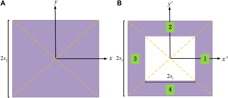
FIGURE 1. The sketch map of the square thermal cloak (areas 1,2,3,4). (A) Schematic diagram of the area before transformation. (B) Schematic diagram of the transformed thermal invisibility cloak.
Two approaches will be given to find the thermal conductivities of the square thermal cloak as follows. The first one is a direct method. To illustrate how the transformation equation of each region is obtained, consider the following case Figure 2A: take a point x on a line segment, the length of which is l. When the segment is compressed to a length of

FIGURE 2. Schematic diagram of compressed line segment. (A) Original line segment. (B) Compressed segment.
Figures 3A, B are the schematic diagram of the area 1 before and after the transformation respectively. Take the left triangle area’s median line, as Figure 4A shows, for example. For the first step shifting the whole segment to the right by
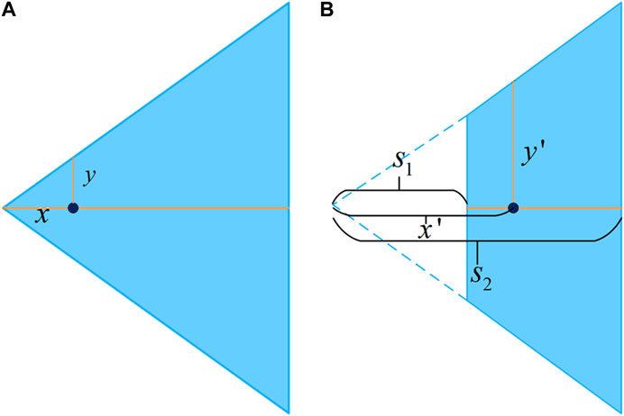
FIGURE 3. The schematic diagram of the transformation of the area 1. (A) Area 1 before transformation. (B) Transformed area 1.
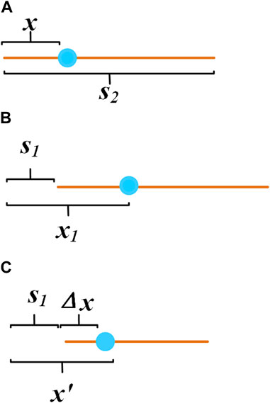
FIGURE 4. Shift the whole segment to the right by
Second, compress the line segment into
According to formula 6, it is obtained:
Simultaneous Eqs 7–9, it could be obtained:
It can be known from similar triangles:
From the above example, it is easy to find that the transformation formula of area 1 is as follows:
In area 1, the Jacobian matrix
In a similar way, the transformation formula and the Jacobian matrix of areas 2, 3, and 4 could be found as the formulae 14, 15, and 16:
The corresponding Jacobian matrixes of areas 2, 3, and 4 are respectively as the formulae 17, 18, and 19:
Finally, the thermal conductivities
The above is the direct way to get the thermal conductivity of the square thermal cloak.
The second way is using a rotation matrix to figure out the thermal conductivity of the four areas. The areas 2, 3, and 4 can be obtained by rotating the area1 counterclockwise by 90°, 180°, 270°. The rotation process can be implemented by the rotation matrix.
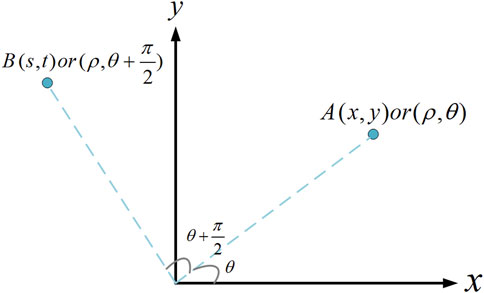
To begin with, let us introduce the rotation matrix P by the flowing example. Consider the situation shown in Figure 5: rotate point A 90° counterclockwise to get point B.
The coordinates of point A are:
where x and y indicate the horizontal and vertical coordinates of point A in the Cartesian coordinate system. ρ, θ are the polar diameter and polar angle of point A in the polar coordinate system.
The coordinates of point B are:
where s and t indicate the horizontal and vertical coordinates of point B in the Cartesian coordinate system.
The matrix form is used to clarify the relationship between A and B:
P is the rotation matrix, which mean a transformation of rotating counterclockwise by 90°. For the area 1, the transformation formula is:
The transformation equation of area 2 can be obtained by rotating the transformation equation of area 1 90° counterclockwise. Multiply both sides of formula 28 by the rotation matrix P:
B and B’ are obtained by rotating A and A’, so we can get:
Take the formula 30 into the formula 29:
Let
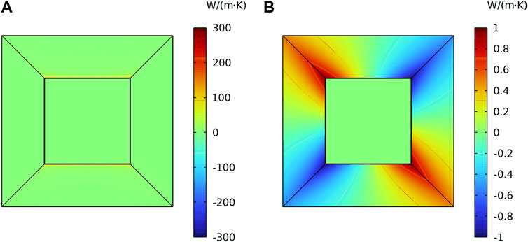
In a similar way, by multiplying the rotation matrix P, the transformation equations of areas 3 and 4 can be found. Then, the thermal conductivity of each transformation space is calculated by formula 4. The results of the direct method and the rotation matrix method are the same. The two methods’ principles are geometric transformation and matrix rotation respectively. The physical natures are the same, only the mathematical means are different. The cloud map of the thermal conductivity coefficient of the thermal cloak is drawn in Figure 6. Figure 6A is
The above thermal cloak is at the origin of the frame. Furthermore, the thermal conductivity of a thermal cloak at any position is calculated by introducing position parameters a, b. Move the coordinate system:
The transformation equations of area 1 are:
Let
The corresponding Jacobian matrix and the thermal conductivity of area 1 at any position are:
In a similar way, in the areas 2, 3, and 4, the thermal conductivity of a thermal cloak at any position can be obtained.
Simulation Verification
To verify the theoretical results of the above derivation, we use COMSOL to implement the simulation. The square-shaped thermal cloak is built in the heat transfer module. Set
Verification of One Thermal Cloak Cell
For one thermal cloak, the first thermal boundary conduction is as Figure 7 shows, the left boundary is set to be 1000k, and the right boundary is set to be 0k. The upper and lower boundaries are set as thermal insulation. The Figure 7A is the heat flux direction, and the Figure 7B shows the diagram of isotherm. It is found that the heat flow stably flows around the heat cloak. It realizes the function of the thermal cloak.
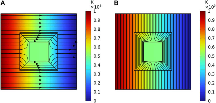
FIGURE 7. The heat flux direction and the diagram of isotherm of one cloak under the first thermal boundaries. (A) The heat flux direction. (B) The diagram of isotherm.
Another is a diagonal thermal boundary, as Figure 8 shows. The upper right corner is set as 1000k, and the lower left corner is set as 0k. Other boundaries are set as insulation. The Figure 8A is the heat flux direction, and the Figure 8B shows the diagram of isotherm. Besides, the position of the diagonal heat source is changed, so that the heat source is not on the diagonal of the heat cloak. The Figure 9A is the heat flux direction, and the Figure 9B shows the diagram of isotherm. It shows that the cloak acts as a shield against the heat flow.
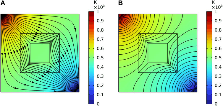
FIGURE 8. The heat flux direction and the diagram of isotherm of one cloak under the second thermal boundaries. (A) The heat flux direction. (B) The diagram of isotherm.
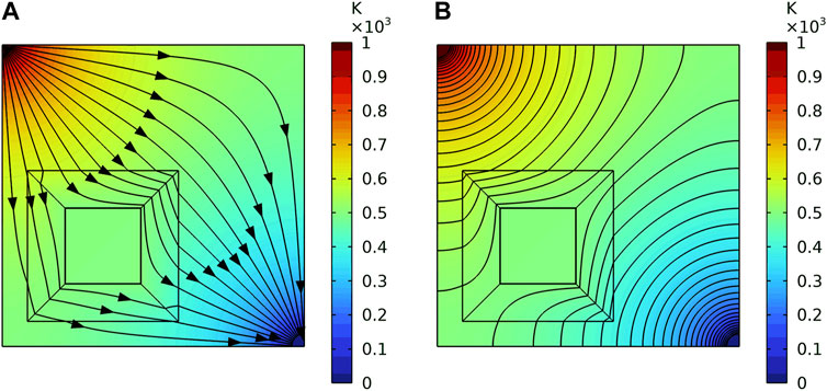
FIGURE 9. The heat flux direction and the diagram of isotherm of one cloak under the second thermal boundaries when the heat source is not on the diagonal of the heat cloak. (A) The heat flux direction. (B) The diagram of isotherm.
Verification of a Periodic Plate With Thermal Cloak
As shown above, by introducing the position parameters a, b, the thermal conductivity tensor of the thermal invisibility cloak at any position can be obtained. According to this, the 8 × 8 periodic plate is built in the transfer module. The thermal conductivities of each cloak are set as deduced.
For the plate, similar to one thermal cloak, two kinds of the thermal boundaries are set. Figure 10 and Figure 11 are the simulation results of the two thermal boundaries respectively. The Figure 10A is the heat flux direction, and the Figure 10B shows the diagram of isotherm under the first thermal boundary. It indicates that the heat flows from the left to the right, and steadily bypasses each thermal cloak. The temperature gradient and heat flow inside each cloak are 0. The Figure 11A is the heat flux direction, and the Figure 11B shows the diagram of isotherm under the diagonal thermal boundary. The heat flows steadily bypass each heat cloak. The heat flow in the center of the periodic plate is 0 and the closer to the diagonal heat source, the denser the isotherm. It proves that each cloak in the plate has the function of avoiding heat flow.
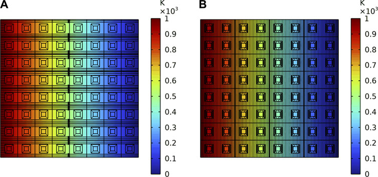
FIGURE 10. The heat flux direction and the diagram of isotherm of the periodic plate under the first thermal boundary. (A) The heat flux direction. (B) The diagram of isotherm.
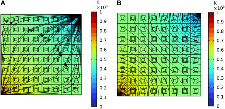
FIGURE 11. The heat flux direction and the diagram of isotherm of the periodic plate under the second thermal boundary. (A) The heat flux direction. (B) The diagram of isotherm.
The position parameters a and b are not considered to prove their necessity. Two of the same kinds of thermal boundaries are set. Figures 12A, B are the heat flux direction under the two thermal boundaries when the position parameters a and b are abandoned. We know that when the position parameters a and b are not considered, the heat flow cannot stably bypass each thermal invisibility cloak. It can be found that the heat flux inside the cloaks that are located in the first column on the left and the last row on the bottom are closest to 0. That is because the thermal conductivity coefficient of the thermal invisibility cloak at those locations only changes one direction when transforming coordinates. As a result, the position parameters are not even a consideration, the heat cloak at these locations can still play a role in avoiding heat flux. Therefore, when arranging the thermal invisibility cloak periodically, the position parameters a and b must be considered.
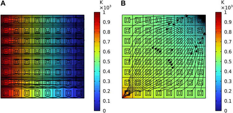
FIGURE 12. The heat flux direction of the periodic plate under two thermal boundaries when the position parameters are abandoned. (A) Under the first thermal boundary. (B) Under the second thermal boundary.
Discussion
Two methods have been given to construct the thermal conductivities of the square thermal invisibility cloak. The cloud map of the thermal conductivity coefficient of the thermal cloak has been drawn. Besides, by introducing the position parameters into the calculation of the thermal conductivity coefficient, the cloaks were arranged periodically so that they can manipulate heat flow in a larger area. The heat insulation function of both the single thermal cloak and the thermal cloak periodic plate were tested under different heat boundary conditions using COMSOL Multiphysics.
The results show that both the single thermal and the thermal cloak periodic plate have the function of avoiding heat flow under different heat boundary conditions. The heat fluxes travel around the inner domain with good thermal stealth effect. To prove the necessity of the position parameters, the comparative verification is done. The results show that the heat flow can stably bypass each thermal invisibility cloak only when the position parameters are considered.
In engineering application, vibration reduction and heat insulation have always been the focus of research. Phonon crystal plates can be used to reduce response. How to combine the phonon crystal plate with the thermal cloak periodic plate to play the role of shock absorption and heat insulation at the same time is worthy of further study.
Data Availability Statement
The original contributions presented in the study are included in the article, further inquiries can be directed to the corresponding author.
Author Contributions
YYS conducted major research work and wrote this paper. YC and XY directed and participated in the discussion of the research work. YL directed the overall research work and guided the writing of the thesis. All authors contributed to the article and approved the submitted version.
Funding
This work was supported by the National Science Foundation of China (Grant No. 52192633).
Conflict of Interest
The authors declare that the research was conducted in the absence of any commercial or financial relationships that could be construed as a potential conflict of interest.
References
1. Zhang, Z, Xu, L, Qu, T, Lei, M, Lin, ZK, Ouyang, X, et al. Diffusion Metamaterials. Nat Rev Phys (2023) 5:218–35. doi:10.1038/s42254-023-00565-4
2. Yang, S, Wang, J, Dai, G, Yang, F, and Huang, J. Controlling Macroscopic Heat Transfer With thermal Metamaterials: Theory, Experiment and Application. Phys Rep (2021) 908:1–65. doi:10.1016/j.physrep.2020.12.006
3. Pendry, JB, Schurig, D, and Smith, DR. Controlling Electromagnetic Fields. Science (2006) 312:1780–2. doi:10.1126/science.1125907
4. Fan, C, Gao, Y, and Huang, J. Shaped Graded Materials With an Apparent Negative Thermal Conductivity. Appl Phys Lett (2008) 92:251907. doi:10.1063/1.2951600
5. Li, J, Gao, Y, and Huang, J. A Bifunctional Cloak Using Transformation Media. J Appl Phys (2010) 108:074504. doi:10.1063/1.3490226
6. Narayana, S, and Sato, Y. Heat Flux Manipulation With Engineered Thermal Materials. Phys Rev Lett (2012) 108:214303. doi:10.1103/PhysRevLett.108.214303
7. Schittny, R, Kadic, M, Guenneau, S, and Wegener, M. Experiments on Transformation Thermodynamics: Molding the Flow of Heat. Phys Rev Lett (2013) 110:195901. doi:10.1103/PhysRevLett.110.195901
8. Mao, F, Li, T, Huang, M, et al. Research and Design of Heat Cloak With Non-Conformal Arbitrary Cross-Section. Acta Phys Sin (2014) 63:01. doi:10.7498/aps.63.014401
9. Li, Y, Shen, X, Wu, Z, Huang, J, Chen, Y, Ni, Y, et al. Temperature-Dependent Transformation Thermotics: From Switchable Thermal Cloaks to Macroscopic Thermal Diodes. Phys Rev Lett (2015) 115:195503. doi:10.1103/PhysRevLett.115.195503
10. Xia, G, Yang, L, Kou, W, et al. Design and Research of Three-Dimensional Thermal Cloak With Arbitrary Shape Based on the Transformation Thermodynamics. Acta Phys Sin (2017) 66:10. doi:10.7498/aps.66.104401
11. Xia, G, Yang, L, and Kou, W. Design and Simulation of Square-Shaped Thermal Cloaks With Arbitrary Angles. Journal Naval University Engineering (2018) 30:02. doi:10.7495/j.issn.1009-3486.2018.02.017
12. Sha, W, Xiao, M, Zhang, J, Ren, X, Zhu, Z, Zhang, Y, et al. Robustly Printable Freeform Thermal Metamaterials. Nat Commun (2021) 12:7228. doi:10.1038/s41467-021-27543-7
13. Li, Z, Wang, X, and Li, Y. The Band gap Variation of a Two Dimensional Binary Locally Resonant Structure in Thermal Environment. AIP Adv (2017) 7:1. doi:10.1063/1.4973723
14. Zhu, Y, Li, Z, and Li, Y. The Lamb Wave Bandgap Variation of a Locally Resonant Phononic Crystal Subjected to Thermal Deformation. AIP Adv (2018) 8:5. doi:10.1063/1.5026523
15. Milton, GW, Briane, M, and Willis, JR. On Cloaking for Elasticity and Physical Equations With a Transformation Invariant Form. New J Phys (2006) 8:248. doi:10.1088/1367-2630/8/10/248
16. Shen, X, and Huang, J. Transformation Thermotic: Thermal Metamaterials and Their Applications. Acta Phys Sin (2016) 65:17. doi:10.7498/aps.65.178103
Keywords: thermal invisibility, periodic plate, thermal metamaterials, cloak, coordinate transformation
Citation: Sun Y, Chai Y, Yang X and Li Y (2023) The Thermal Conductivity Coefficient of a Square Thermal Invisibility Cloak Cell and Its Application in Periodic Plate. Aerosp. Res. Commun. 1:12099. doi: 10.3389/arc.2023.12099
Received: 23 September 2023; Accepted: 31 October 2023;
Published: 20 November 2023.
Copyright © 2023 Sun, Chai, Yang and Li. This is an open-access article distributed under the terms of the Creative Commons Attribution License (CC BY). The use, distribution or reproduction in other forums is permitted, provided the original author(s) and the copyright owner(s) are credited and that the original publication in this journal is cited, in accordance with accepted academic practice. No use, distribution or reproduction is permitted which does not comply with these terms.
*Correspondence: Yueming Li, bGl5dWVtaW5nQG1haWwueGp0dS5lZHUuY24=
 Yanyan Sun
 Yijun Chai
 Yueming Li