Abstract
An optical attitude (scanning angle and spin rate) measurement method for terminal sensitive projectile in vertical wind tunnel test is proposed. The principles of measuring scanning angle and spin rate simultaneously depend only on one fixed camera are presented in detail. The measurement processes, which mainly includes preparation, image acquisition, segmentation of projectile, contour extraction, and estimation of attitude, are described accordingly, and the key techniques involved in each step are expanded exactly. Moreover, the measurement errors are analyzed thoroughly. The advantages of the novel method is analyzed as follow: first, the mathematical model for calculating scanning angle of a steady-state terminal sensitive projectile is derived for the first time in literature, which makes it possible to measure scanning angle from images recorded by only a fixed camera; second, the algorithms of estimating scanning angle and spin rate depend only on the line-segments of the perspective cylinders in images are designed, which significantly improve the attitude measurement accuracy. Experiment was also conducted in laboratory to verify the novel method.
Introduction
Terminal-sensitive projectile, also called sensor-detonated projectile, is a kind of cluster bomb which contains many smaller bombs and is very disruptive. It can be launched by cannons, long-range rockets or aircraft. When flying to the target over a certain height, the smaller bombs are thrown and they can automatically detect and recognize the targets and make accurate attacks when they reach steady-flying (or steady-scanning) state after a deceleration stage. Since the detection and attack operations are performed during the steady-scanning stage, the steady-scanning attitude such as falling velocity, scanning angle, and spin rate are very important parameters that affecting the performance and hit probability of the terminal sensitive projectile [1]. Therefore, it is necessary to measure the steady-scanning attitude of the terminal sensitive projectile through either vertical wind tunnel test or field test.
There are already many sensors [2] developed to measuring the steady-scanning attitude of the projectile. According to the installation position, existing sensors can be classified into two categories: projectile-borne sensors and non-projectile-borne sensors. Projectile-borne sensors [3–17] such as accelerometers, gyroscopes, geomagnetic sensors, and solar sensors are generally installed inside the body of the projectile. Schuler et al [3] proposed to use linear accelerometers to measure the spin rate of rotating objects. Without loss of generality, three or more linear accelerometers were placed at different axis of the projectile coordinate system, the linear acceleration along each axis were measured during high-speed flight, and the spin rate was thereby calculated based on the collected acceleration information. This type of sensors has the advantages of low cost, low-power consumption, and high reliability, etc. [4]. However, as the number of the linear accelerometers increases, the installation error increases, and more space is needed to place them which is not very practical because the body space of the projectile is limited. Moreover, the error of the calculated spin rate increases dramatically over time.
Gyroscopes, which often employed in inertial navigation systems, are another type of projectile-borne sensors. The traditional gyroscopes can be used to measure the scanning angle and spin rate of the projectile. They have the features of working all the time, and high accuracy and high stability in short term. Whereas, their volumes are usually large and their overload capacity are weak [5]. Recently, MEMS (Microelectromechanical system) is applied to the gyroscopes, and new MEMS gyroscopes, which have no moving parts, are developed to measure the attitude of the projectiles. The new MEMS gyroscopes usually have small volume and low cost. But their measuring ranges are often small and their long-term stability is low, the measuring error of the attitude increases over time as the linear accelerometers [6, 7].
Geomagnetic sensor, which obtain the attitude information through measuring the magnetic field vector information, is one of the most concerned research focuses among all attitude measuring sensors for spin missiles. Zhou et al. [8] presented an attitude calculation method based on geomagnetic sensor by establishing the geomagnetic model and considering the characteristics of steady scanning motion of terminal sensitive projectile. Deng et al. [9] studied a real-time roll angle estimation method based on phase-locked loop on signals from single-axis magnetometer for spinning projectile. The novel method is less dependent on the amplitude and able to reduce effect from geomagnetic blind area. Geomagnetic sensor owns the advantages of passive sensing, high sensitivity, as well as low power and cost [10]. Whereas, its accuracy depended on accurate geomagnetic model which usually difficult to obtain and vulnerable to environmental interference.
Solar sensor measures the spin rate, nutation angle and precession angle through recorded solar azimuth which is defined as the angle between missile rotational axis and the sunlight pass through the missile center. Gui and Yang [11] presented a scheme of practicable digital telemetering system for measuring the attitude of projectile in flight based on the principle of solar aspect angle. The system had been used in practice for the test of projectiles which survive as high as 18 thousand g. Although the principle of solar sensor is simple, it is severely limited by the sunlight and weather conditions, and its measuring accuracy is not high.
Owing to the limitations of each type of projectile-borne sensors, the multi-sensor systems which combine the accelerometers, gyroscopes, geomagnetic sensors and solar sensors are thereby designed [12–17]. Change et al. [12] estimated the attitude of projectiles using magnetometers and accelerometers. Harkins et al. [13] combined the solar sensors and magnetic sensor to measure the spin rate and scanning angle of spinning projectiles. Cao et al. [14] put forward a low-cost attitude detect system which consists of geomagnetic sensor and micro silicon gyro. Huang et al. [15] employed magnetometer, MEMS accelerometer and gyroscope to estimate attitude information. Since the multi-sensor systems can overcome the shortage of each type of sensors, either the robustness or the accuracy of the measuring system is improved significantly.
Non-projectile-borne sensors [1, 18–23], such as the optical measurement system (also known as high-speed video measuring technology or image-based method), Radar and global navigation satellite system (GNSS) etc., are usually placed outside of the body of the terminal sensitive projectile. The GNSS includes American GPS, Russian GLONASS, European Galileo, and Chinese BDS. Among them, the American GPS system is most widely used. Deng et al. [18] adopted a GPS (Global Positioning System) receiver with a single side-mounted antenna to detect the roll angle and rotational speed of a spinning vehicle A Frequency-Locked Loop (FLL) assisted Phase-Locked Loop (PLL) is designed to obtain the attitude information from GPS signals. Cao et al. [19] studied the roll angle calculation method based on Geomagnetic sensor and GNSS to meet the needs of high-frequency and high-accuracy roll angle measurement for the high-spin projectile. Because of limited body space of the projectile, either he layout of the baseline or the installation of the receiver is restricted, the measuring accuracy of the GNSS is not high.
Radar can also be used to measure the spin rate of high-spin projectile. Ferguson et al. [20] employed Doppler radar to measure the steady-state spin rates of the kinetic energy projectiles. Li et al. [21] presented a new method to measuring the rotation velocity of small arms projectiles by transforming Doppler radar data to the time domain on the premise of eliminating corresponding noise and clutter signals in the frequency domain. The disadvantage of Radar applied to measure the steady-state spin rates of terminal-sensitive projectile is that slot need to be carved at the bottom of the projectile.
Optical measurement instruments/systems are widely used in modern weapon test. Due to high-speed video technique, it is possible to smoothly view the steady-state rotation of a projectile spinning at 300 revolutions per second (HZ) with a camera recording at a rate of 10,000 frames per second. Gao et al. [22] used two cameras to measure the scanning angle and spin rate of two different types of terminal-sensitive projectiles in vertical wind tunnel test, and compared the measuring results with field test. Yakimenko et al. [1] presented a scheme of measuring spin rate of marked projectiles using computer vision analysis method. Black and white longitudinal stripes along the direction of the projectile axis should be painted on the surface of the projectile in advance. By counting the stripe pixel column of the recorded images, the spin rate of the projectile can be obtained exactly. Zhao et al. [23] proposed a model-based optimization algorithm to estimate the motion parameters of projectile from the recorded images from stereo linear array image. The optimal motion parameters are achieved by matching the stereo projection of the projectile and that of the same size 3D model. The optical measurement instruments/systems usually have higher accuracy than other sensors in spin rate measurement, and are especially suitable for wind tunnel test. Whereas, they are often lack of precision in scanning angle measurement.
In this paper, an optical attitude measurement method for terminal sensitive projectile in vertical wind tunnel test is proposed. The optical measurement method is extremely simple since only one high-speed camera is employed. However, both scanning angle and spin rate can be measured accurately by using the novel method. The measurement principle, measurement process, and measurement errors are presented in detail. Compared with existing optical attitude measurement methods, the contribution of the novel method can be analyzed in two aspects: first, the mathematical model for calculating scanning angle of a steady-state terminal sensitive projectile is derived, which makes it possible to measure scanning angle from images recorded by only a fixed camera; second, the algorithms of estimating scanning angle and spin rate depend only on the line-segments of the perspective cylinders in images are designed, which significantly improve the measurement accuracy.
Measurement Principle
Steady-Scanning Model
The experiment setup is shown in Figure 1. The length of the experimental section of the vertical wind tunnel is about 6.5 m, the diameter of the contraction section of the vertical wind tunnel is Ø4.5 m, the maximum wind speed for the experimental section is about 50 m/s (meter per second), and the minimum wind speed is about 5 m/s. During experiment, the terminal-sensitive projectile is hung in the air through a flexible rope over a pulley and rotate around a plumb axis, the steady spin rate ranges from 4 to 6 r/s (revolutions per second) to about 30 r/s (for different types of terminal-sensitive projectiles). It is widely recognized that the steady-state trajectory of a terminal-sensitive projectile follows an Archimedean spiral. However, at any given moment, the trajectory can also be visualized as a virtual cone. The generator line of this cone corresponds to the axis of the projectile, while the axis of the cone aligns with the plumb axis. The vertex of the cone represents the point of intersection between the plumb axis and the projectile’s axis. Therefore, the scanning angle at each moment can be understood as the half-cone-angle of the corresponding virtual cone. Consequently, measuring the real-time scanning angle is equivalent to determining the cone-angle of the corresponding virtual cone.
FIGURE 1
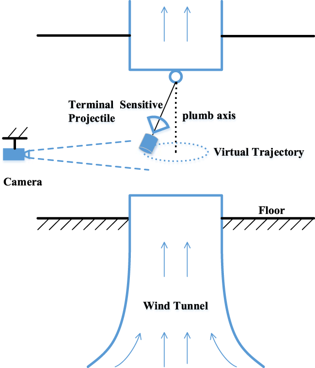
Schematic diagram of vertical wind tunnel test.
Layout of Optical Measurement System
The configuration of the optical measurement system is particularly simple, as shown in Figure 1, only one high-speed camera is employed to record images of the terminal-sensitive projectile in flight. The camera can be installed on the wall, or on a tripod, but should be in a horizontal orientation and the optical axis of which should be orthogonal to the plumb axis. Moreover, the distance of the camera to the plumb axis should be far greater than the radius of the virtual cones, and some high-lumen LED lamps should be placed around the vertical wind tunnel to provide adequate lighting for the optical system.
Principle of Measuring Scanning Angle
As described in Steady-Scanning Model section, the steady-state trajectory of the terminal-sensitive projectile can be visualized as a virtual cone at each moment. Consequently, capturing the steady-scanning trajectory of the projectile on an image plane is essentially projecting the virtual cone onto that plane. In Figures 2A, B, the virtual cone at a specific moment is represented by a blue dashed line, with the generator line depicted as a blue solid line. The vertex of the cone is denoted as point S. To establish a coordinate system for the virtual cone, we introduce the coordinate system , the origin is located at the base center of the virtual cone, the axis is coincides with the axis of the virtual cone, and the axis is parallel to the axis of the camera coordinate system. The intersection of the base border of the virtual cone and the axis is marked by points C and D. Furthermore, the camera coordinate system is defined, with the origin representing the optical center of the camera, the axis is parallel to the axis , and the axis , which aligns with the optical axis of the camera, is orthogonal to the axis and intersects at point .
FIGURE 2
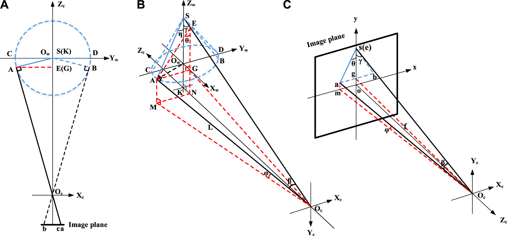
Imaging principal of the steady-scanning trajectory of the terminal-sensitive projectile in vertical wind tunnel test. (A) Top-down view of the ray of the imaging system. (B) Isometric view of the ray from the optical center of the camera to the scene. (C) Isometric view of the ray from the optical center of the camera to the image plane.
According to the principles of Descriptive Geometry, the projection of a cone is an isosceles triangle, the two congruent legs of which are projection of the limit elements on the projection view. As shown in Figure 2C, The coordinate system o is the image coordinate system, the origin o is projection of the optical center , the axis is parallel to the axis , and the axis is parallel to the axis . The isosceles triangle on the image plane is projection of the virtual cone, and the two congruent legs and are projections of the limit elements and which are tangent to the rays and (it should be noted that the projection of the base of the virtual cone may be not a line since the base would not be coincident with the plane of , thereby the projection of the virtual cone may be not a triangle, to simply the analysis, the triangle is still used as instead here because the simplification does not cause any loss of the accuracy). Since the angle between any element on the conical surface and the axis of the cone is the half-cone-angle, if any one of the four angles , , , and is calculated, the scanning angle is obtained accordingly. As a matter of fact, the projections of the two angles and on the image plane are equivalent to the themselves. Unfortunately, the projections of point C and point D cannot be identified on the image plane, so these two angles cannot be solved. The projections of the two angles and are the two angles and on the image plane, respectively.
Because there is perspective transformation between the angles and their projections, and the perspective transformation is difficult to obtain, the true values of the angles cannot be derived directly. In this section, both ray trace method and geometric analysis are employed to compute the true values (the values of the two angles and are equal, only the angle is computed here). As shown in Figure 2B, create an auxiliary plane through point A that is perpendicular to the axis and intersects with the ray and the axis and at the points E, G and N, respectively. Then connect those intersection points and draw five auxiliary lines , , , and with red dotted line. Since the plane where the triangle is located is perpendicular to the axis , it is parallel to the image plane, hence the angle is equal to its projection, i.e., . Furthermore, according to the ray trace theory, the projections of point S and point E are coincident, and the projection of point G is located at the midpoint of the line on the image plane, if the angles is marked as , thus . Obviously, the angle is not equal to the angel , i.e., , hence . That is the value of the angle cannot be simply replaced with the value of its projection .
Draw an auxiliary line AM through point A that is perpendicular to the plane and intersects at point M with red dotted line (Figure 2B). Meanwhile, draw an auxiliary line am through point a that is perpendicular to the axis x and intersects at point m with red dotted line (Figure 2B) According to the ray trace theory, the point m is projection of point M and there is a virtual ray between point m and point M (connected with a red dotted line). Moreover, connect the point A and point with a black dotted line (Figure 2B). And mark the angle as , the angle as , the angle as , the angle as , and the length of the ray as L. As shown in Figure 2B, according to the Pythagorean theorem,
In addition, according to the geometric relationship,
By combing Formulas 1, 2, the angle can be computed
According to Formula 3, if the three angles , and are solved, the angle can be calculated exactly.
Assume the focal length of the camera is f, the pixel sizes are and along the x and y directions respectively, and the two-dimensional (2D) pixel coordinate of point a is . As shown in Figure 2C, according to the Pythagorean theorem,where the operator means taking absolute value. According to the Cosine theory,
In addition, , by combining Formulas 4, 5, it can be inferred that
According to Formula 6, the three angles , and are functions of the six variables f, , , , and . The 2D pixel coordinate of point a and the angle can be achieved through image analysis exactly. The focal length f and the pixel sizes and can be obtained from the handbook of the high-speed camera. Thus, the three angles , and can be computed exactly, and the value of half-cone-angle can be obtained.
Note that the half-cone-angle can be achieved only when the terminal-sensitive projectile rotates to position A and B as shown in Figure 2A, if rotates to other position, Formulas 1, 3 are not valid any more, thus, the half-cone-angle cannot be solved. That is in one complete revolution, the real time scanning angle of the terminal-sensitive projectile at two points can be measured in vertical wind tunnel test.
Principle of Measuring Spin Rate
Like the moon whose rotation rate is the same as the time it takes to make one revolution, the terminal-sensitive projectile rotates on its own axis in the same period of time that revolves around the plumb axis (Figure 1) during the steady-scanning stage in the vertical tunnel test, thus, the steady-state spin rate can be achieved by measuring either the rotation rate or the revolution speed of the terminal-sensitive projectile [1, 22].
The revolution speed can be solved by recording the time taken to make one revolution, or by counting the number of revolutions within a given time. The former can be seen as computing the real-time velocity while the former can be seen as computing the average velocity. Different from previous method that employs two cameras to track the revolution speed of the terminal-sensitive projectile, in this paper, only one camera is employed. As shown in Figure 3, the steady-state motion of the terminal-sensitive projectile on the image plane is similar to the pendulum motion which is a typical oscillating motion. Thus, the projection of the axis of the projectile must be coincident with the y-axis periodically. Mark the time of the coincidence as where , thereupon the real-time velocity at time can be expressed asand the average velocity can be expressed as
FIGURE 3
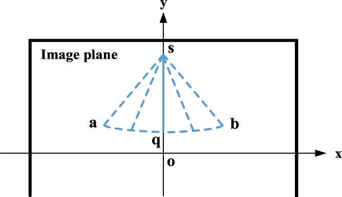
Imaging of the steady-state motion of the terminal-sensitive projectile.
The rotation rate can be achieved by tracking features such as the natural texture on the surface of the terminal-sensitive projectile, pattern painted or drawn manually, corners, or specialized targets that widely used in optical measurement [1, 23]. Since the terminal-sensitive projectile rotates on its own axis, the shapes and coordinates of the features at different position are different when view from the optical axis as shown in Figure 4. Furthermore, the rotation rate is equal to the revolution speed, hence the shapes and coordinates of the features at the same position in different circles of rotation are almost identical. Therefore, the rotation rate can be obtained by tracking the shapes and coordinates of the features at some positions where they can be seen clearly using feature tracking algorithms or deep learning algorithms.
FIGURE 4
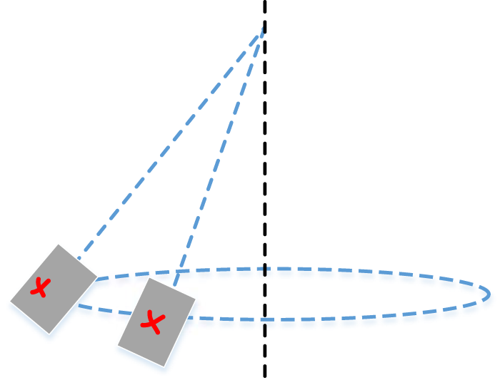
View of the pattern “” drawn on the surface of the terminal-sensitive projectile during rotation.
Measurement Process
The measurement process mainly includes five steps: preparation, image acquisition, segmentation of projectile, contour extraction, and estimation of attitude, as shown in Figure 5. The key techniques involved in each step will be presented in detail.
FIGURE 5
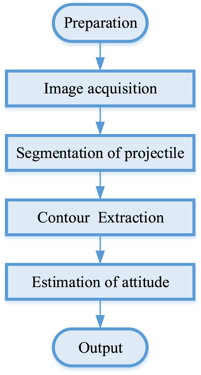
Flowchart of measurement process.
Preparation and Image Acquisition
Before image acquisition, the camera should be adjusted to a ready state: adjust the camera to be horizontal by means of a spirit level, and align the vertical axis of the crosshair of the camera to be coincident with the stationary flexible rope which hanging the terminal-sensitive projectile in the air (the flexible rope is coincident with the plumb axis when it is in stationary state). Then record an image of the static scene as background image for segmentation step. Finally, begin to record images when the motion of the terminal-sensitive projectile is in a steady state.
Segmentation of Projectile
Segmentation of the projectile is essentially detecting moving object from complex scenes which is an important topic in the field of computer vision. Many methods, such as the frame difference [24], background subtraction [25], optical flow [26], or deep learning-based method [27], etc., have been proposed for moving object detection with either a stationary camera or a moving camera. Since the camera is fixed during the measurement, background subtraction is adopted here.
The background subtraction is the most effective method for detecting moving objects in video or a series of images [24]. The core of background subtraction is building the background model/image. In this paper, the background image is recorded in advance as mentioned in Preparation and Image Acquisition section. Suppose the gray value of the background image is given by , and the gray value of the frame at time t is , where x and y are values of the 2D coordinate of pixel. The binary image operation results of background subtraction can be defined aswhere the operator means taking absolute value, and T is the threshold. According to Formula 9, for each point in the image, if the difference value is greater than the threshold, then put the point as a foreground pixel, otherwise, regarding the point as a background pixel.
Because the flexible rope and parachute that linked with the terminal-sensitive projectile also rotate synchronously, they are also extracted during the segmentation. To separate the terminal-sensitive projectile from the flexible rope and parachute, after threshold, the morphological open operator is applied to the binary image several times until the projectile is separated completely. Finally, cluster the remain pixels in the binary image base on 4-neighbors and pick out the largest cluster which is the pure projectile.
Contour Extraction
The main body of the terminal-sensitive projectile is a cylinder and its projection on the image plane is a perspective 2D cylinder. To determine its orbit in the recorded images, the contour of the perspective 2D cylinder, which generally consists of two line-segments and two elliptic arcs, should be extracted to fit the axis of the cylinder. As accuracy is required for fitting, subpixel edge extraction operators [28] are used to extract subpixel contour points.
Because some of the contour points belong to the line-segments, some belong to the elliptic arcs, and a few belong to noise, it is necessary to separate them. Due to incompleteness, the previous works [29] have proven that the ellipse fitting may be inaccurate only rely on the contour points belong to the elliptic arcs. Therefore, the contour points belong to the elliptic arcs are not used here, only the contour points belong to the line-segments are adopted. To distinguish the contour points that belong to the line-segments, the random sample consensus (RANSAC) algorithm [30] is employed. The basic procedure is as follow:
Step 1Randomly selecting two contour points from the extracted N contour points above;
Step 2Calculating a line with the two points selected in Step 1;
Step 3Calculating distance of the other contour points to the line obtained in Step 2, if the distance of a contour point is smaller than the threshold , it is labeled as an inlier, otherwise labeled as an outlier;
Step 5Selecting the two lines with the most inliers.To ensure accuracy, the threshold in the above procedure is set to one pixel, i.e., .
Estimation of Attitude
As analyzed in Principle of Measuring Scanning Angle section, the scanning angle can be solved only when the terminal-sensitive projectile rotates to position where the ray is orthogonal to the axis of the projectile. Figure 6 shows an image of a cylinder rotated to that position. It can be seen that the two line-segments are parallel to each other, and the ellipse arcs almost become lines too. Mark the two line-segments as and , the axis of the cylinder as , then . Assume the angles between the line-segments , and the y-axis of the image coordinate system is and , respectively, thus the angle between the axis and the y-axis can be calculated as
FIGURE 6
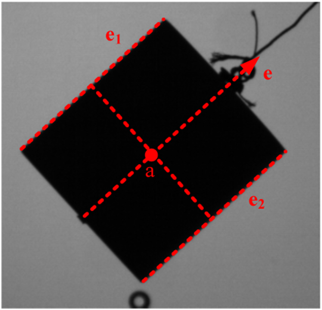
Extraction of line-segments when the ray is orthogonal to the axis of the rotating cylinder.
Once the two line-segments and are fitted, the angles and can be computed exactly, the angle thereby can be solved. That is the axis does not need to be fitted any more.
The position of point a is determined as follow: project the center points of line-segments and to the axis , then take the midpoint of the two projected points on the axis as point a. Because the length of line-segments and are almost equal to each other, the projections of the center points on the axis are almost coincident as shown in Figure 6. Once the position of point a is determined, its 2D coordinate can be achieved exactly. Finally, by combing the parameters (the focal length f and the pixel sizes and ) of the high-speed camera, the scanning angle can be calculated exactly through Formulas 3, 6.
As analyzed in Principle of Measuring Spin Rate section, the steady-state spin rate can be achieved by measuring either the rotation rate or the revolution speed of the terminal-sensitive projectile. To measure the rotation rate, the key point is tracking the features, so the surface of the terminal-sensitive projectile should be illuminated, as shown in Figure 7. Since the feature tracking algorithms have been widely studied and applied in computer vision, the details will not be presented here. The disadvantage of measuring rotation rate by tracking features is that the contours of the cylinder in images may be quite vague (Figure 7), thus the line-segments would be difficult to distinguish or with a low separate accuracy, which would affect the scanning angle measurement accuracy.
FIGURE 7
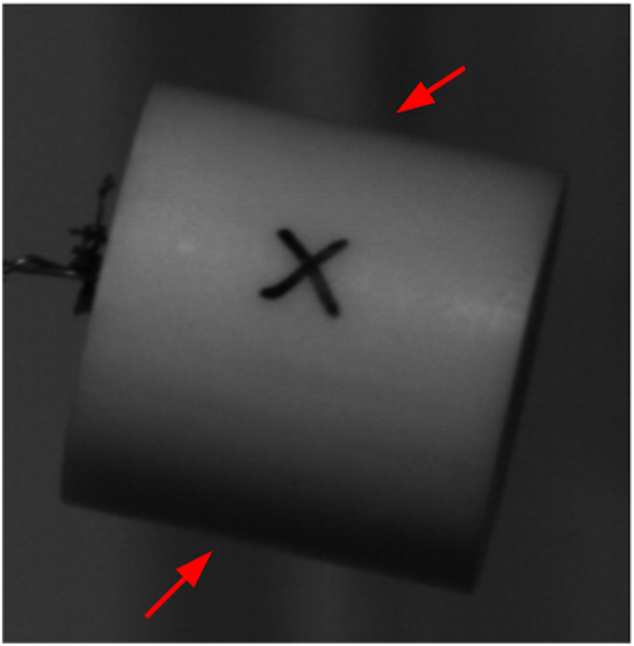
A frame of a rotating cylinder whose surface is marked with an artificial pattern.
To measure the revolution speed, the key is finding out the frames in which the axis of the projectile is coincident with the y-axis of the image coordinate system. As mentioned before, the axis of the projectile is difficult to fit accurately, hence only the line-segments are employed. As shown in Figure 8, due to perspective transformation, the line-segments and would be not parallel to each other while the axis of the cylinder is coincident with the y-axis of the image coordinate system. To judge correctly, the follow formula is developedwhere and are the normalized vector of line-segment and , and is the basic unit vector. For a frame in which the axis of the cylinder is coincident with the y-axis of the image coordinate system, the would be zero in theory. Whereas, it would be a very small value since there are errors. Thus, find out those frames with minimum , then use Formulas 7, 8 to compute the real-time and average velocity.
FIGURE 8
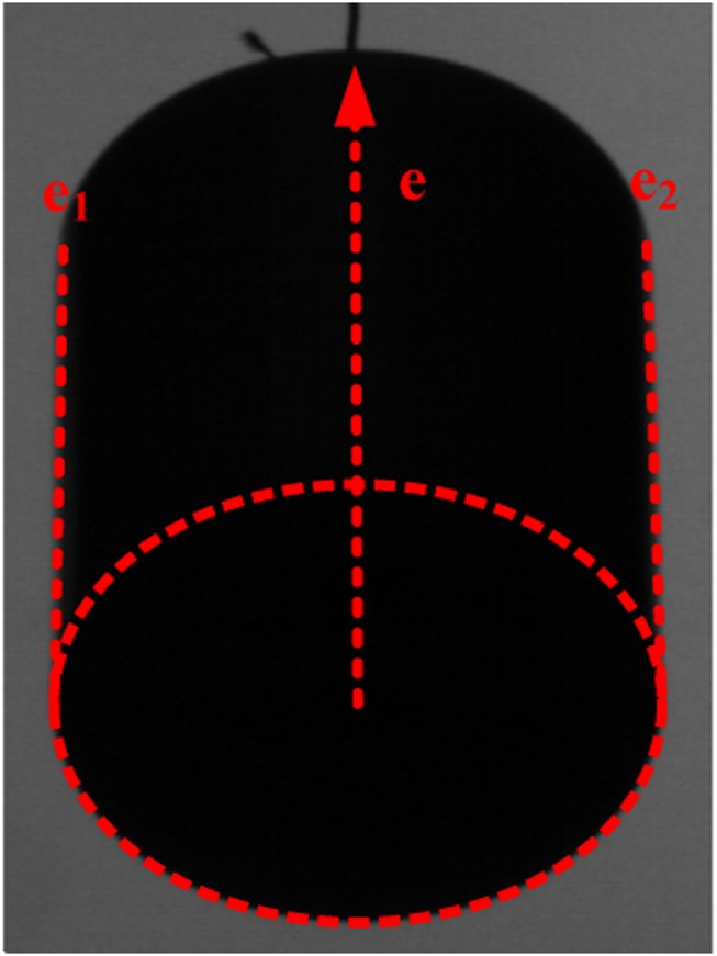
A frame of a rotating cylinder whose axis is coincident with the y-axis of the image coordinate system.
Measurement Error Analysis
Measurement Error of Scanning Angle
There are many factors, such as the error of the focal length f and the pixel sizes and , frame rate, and contour extraction error, etc., may affect the scanning angle measuring accuracy. Since the subpixel edge extraction operators can reach an accuracy of pixel, its influence is omitted. The error of the focal length f and the pixel sizes and may produce systematic error which can be corrected through some calibration procedure, so they are not discussed here. The frame rate has significant influence on the measurement accuracy, so it is discussed in detail. As shown in Figure 9A, a frame should be captured at position A in theory, whereas, it may be missed because there is a time interval between two frames. The maximum error is reached when position A is in a certain position between the two adjacent frames at position A1 and A2. Thus, either the 2D coordinate of point a or the angle on the image would exist an error which would lead to an error of the scanning angle according to Formulas 3, 6.
FIGURE 9
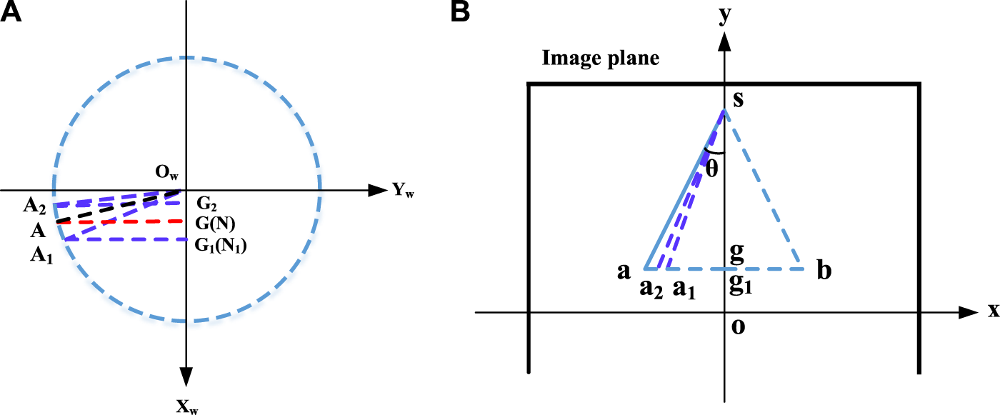
Schematic of measurement error introduced by frame rate. (A) Partial view of the plane in Figure 2B. (B) View of the trajectory on the image plane.
Assuming the frame rate of the high-speed camera is fps, and the spin rate of the terminal-sensitive projectile is r/s, then . That is and . For ease of calculation, only the error at point is calculated and the angle is set to the upper bound , i.e., .
As shown in Figures 2B, C, according to ray trace theory
Draw an auxiliary line through point that is perpendicular to the axis (Figure 9A). Since the point is on the plane , thus . Assuming the projection of point on the image plane is , the 2D coordinates of point a1 is , and the angles is . Then
According to Figure 9A, , hence , then
Moreover, according to the Pythagorean theorem,
Therefore, the 2D coordinate of point a1 can be computed exactly.
Once the 2D coordinate of point a1 is solved, the angle can be calculated according to the Pythagorean theorem as following (Figure 9B)
Finally, a new scanning angle can be calculated by inputting the parameters , , f, , and into Formulas 3, 6, and the measuring error thereby can be obtained as
Measurement Error of Spin Rate
The frame rate and the time measurement error of the high-speed camera, and contour extraction error, etc., may affect the spin rate measuring accuracy. Among them, the frame rate is the major influence factor. As shown in Figure 3, a frame should be captured at position g where the axis of the projectile sg is coincident with the y-axis of the image coordinate system in theory, whereas, it may be missed because there is a time interval between two frames. The maximum error is just a frame. Therefore, the spin rate measurement error is
Experiment
Experiments were conducted in a laboratory to evaluate the proposed method for image segmentation. The experimental setup is illustrated in Figure 10. In the experiment, a terminal-sensitive projectile was suspended in the air using a flexible rope that passed over a pulley and rotated around a plumb axis. The projectile maintained a steady spin at a rate of approximately 3.5 revolutions per second. To ensure adequate illumination, a LED light source was employed. For image recording, a high-speed CMOS camera, specifically the MIKROTRON EoSens 3CXP as shown in Figure 11, was used. The camera has a maximum resolution of 1280 × 1024 pixels, with a pixel size of 8 × 8 μm. The focal length of the camera lens was set to 35 mm, and the camera operated at a frame rate of 1,000 frames per second.
FIGURE 10
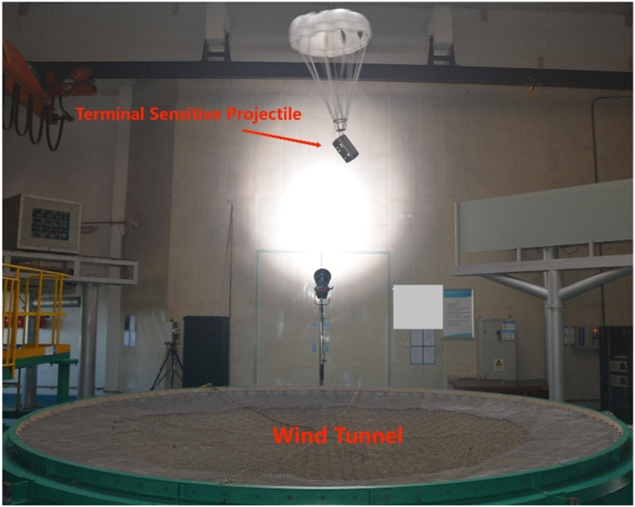
Experiment setup used to test the attitude measurement algorithm in laboratory.
FIGURE 11
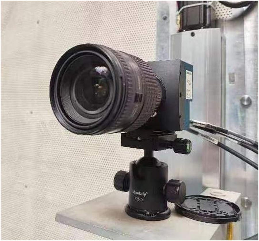
High-speed CMOS camera employed in the experiment.
During the experiment, two lighting schemes were tested to assess their impact on the quality of the captured images. The first scheme involved illuminating the main body of the terminal-sensitive projectile, while the second scheme involved illuminating the surrounding wall. The results showed that the latter scheme produced images with clearer edges compared to the former, which resulted in images with blurred edges. Therefore, the lighting scheme that illuminated the wall was ultimately chosen for further experimentation. The measurement process described in Measurement Process section was followed during the experiment. When the rotating terminal-sensitive projectile reached a steady state, the camera recorded a total of 5,000 images over a duration of 5 s. Figure 12 displays a frame captured from the rotating terminal-sensitive projectile, providing a visual representation of the captured image. Additionally, Figure 13 showcases the extracted axis of the main body of the terminal-sensitive projectile, which was obtained through the image processing and segmentation techniques discussed in the paper. These figures serve to illustrate the effectiveness of the proposed method in capturing and extracting relevant information from images of the rotating terminal-sensitive projectile. The clear edges in the images obtained using the selected lighting scheme contribute to accurate segmentation and subsequent analysis of the terminal-sensitive projectile’s main body.
FIGURE 12
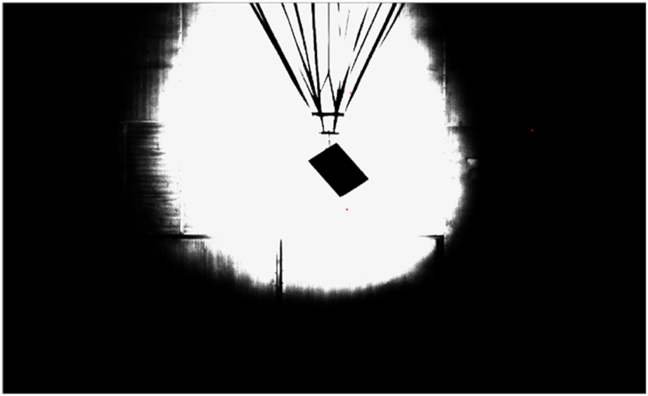
A frame of the rotating terminal-sensitive projectile.
FIGURE 13
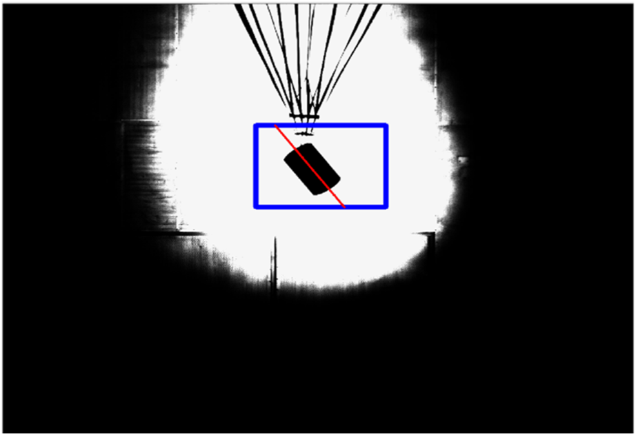
Fitting the axis of the main body of the terminal-sensitive projectile.
The measured scanning angles are depicted in Figure 14. The minimum scanning angle recorded was 37.5°, the maximum scanning angle was 39.2°, and the average scanning angle was 38.3°. The measurement error associated with the scanning angle was found to be less than 0.67°. Similarly, the measured spin rates are shown in Figure 15. The minimum spin rate observed during the experiment was 3.25 revolutions per second (r/s), the maximum spin rate was 3.35 r/s, and the average spin rate was 3.30 r/s. The measurement error for the spin rate was determined to be less than 0.05 r/s. These measurement results highlight the high accuracy achieved by the novel algorithm proposed in the paper. The algorithm effectively captures and analyzes the rotational motion of the terminal-sensitive projectile, providing precise measurements of both the scanning angles and spin rates. The low measurement errors indicate the reliability and robustness of the algorithm in accurately quantifying these parameters.
FIGURE 14
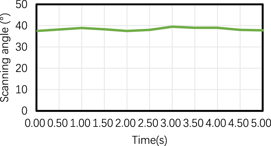
Scanning angle of the rotating terminal-sensitive projectile.
FIGURE 15
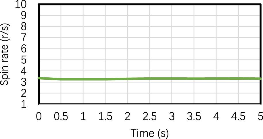
Spin rate of the rotating terminal-sensitive projectile.
Conclusion
Optical measurement instruments/systems are widely used in modern weapon test. They usually have higher accuracy than other sensors in spin rate measurement, whereas lack of precision in scanning angle measurement. In this paper, an optical attitude measurement method for terminal sensitive projectile in vertical wind tunnel test is presented in detail. The optical measurement method is extremely simple since only one high-speed camera is employed. However, both scanning angle and spin rate can be measured accurately by using the novel method.
Compared with existing optical attitude measurement methods, the contribution of the novel method can be analyzed in two aspects: first, the mathematical model for calculating scanning angle of a steady-state terminal sensitive projectile is derived, which makes it possible to measure scanning angle from images recorded by only a fixed camera; second, the algorithms of estimating scanning angle and spin rate depend only on the line-segments of the perspective cylinders in images are designed, which significantly improve the measurement accuracy. The perspective cylinder, which is projection of the terminal sensitive projectile on image plane, is generally consist of two line-segments and two elliptic arcs. It is well known that the ellipse fitting may be inaccurate only rely on the contour points belong to the elliptic arcs. Therefore, only line-segments are adopted to compute both scanning angles and spin rate accurately.
The shortcoming of this paper is that the error of the focal length f and the pixel sizes and are not considered. In fact, the error of those parameters may produce considerable measurement error. Hence, they should be calibrated in advance in practical application.
Statements
Data availability statement
The original contributions presented in the study are included in the article/supplementary material, further inquiries can be directed to the corresponding author.
Author contributions
XY, CG, ZZ, and HW conducted the experiments, XY, YW, and YL wrote the manuscript. All authors contributed to the article and approved the submitted version.
Conflict of interest
The authors declare that the research was conducted in the absence of any commercial or financial relationships that could be construed as a potential conflict of interest.
References
1.
Yakimenko OA Kolsch MN Decker RJ . Method and Apparatus for Computer Vision Analysis of Spin Rate of Marked Projectiles. U.S. Patent 9911046 (2018). p. 3–6.
2.
Shang J Deng Z Fu M Wang ST . Advance and Perspective on Spin Rate Measurement Technology for Guided Projectile. Acta Automatica Sinica (2016) 42(11):1620–9.
3.
Schuler AR Grammatikos A Fegley KA . Measuring Rotational Motion With Linear Accelerometers. IEEE Trans aerospace Electron Syst (1967)(3) 465–72. 10.1109/taes.1967.5408811
4.
Lu YL Pan YJ Li L Liu Y Peng H . Measurement Method of Projectile’s Heading and Pitching Angle Velocities Based on Biaxial Accelerometer. J Chin Inertial Technol (2015) 23:160–4.
5.
Stroezel M Saaro J Stieler B . Wind Tunnel Model Attitude Measurement With a Fiberoptic Gyro. Stuttgart, Germany: Symposium Gyro Technology 1995 (1995). p. 14.
6.
Liu N Su Z Li Q . Design and Experiment of a Novel Bellshaped Vibratory Gyro. Sensors Actuators A: Phys (2016) 238:37–50. 10.1016/j.sna.2015.10.036
7.
Lin Z Fu MY Deng ZH Liu N Liu H . Frequency Split Elimination Method for a Solid-State Vibratory Angular Rate Gyro With an Imperfect Axisymmetric-Shell Resonator. Sensors (2015) 15(2):3204–23. 10.3390/s150203204
8.
Zhou L Liu R Guo R . Attitude Calculation Method of Terminal Sensitive Projectile Based on Geomagnetic Sensor. J Ordnance Equipment Eng (2018) 3:174–7.
9.
Deng Z Shen Q Deng Z Cheng J . Real-Time Estimation for Roll Angle of Spinning Projectile Based on Phase-Locked Loop on Signals From Single-Axis Magnetometer. Sensors (2019) 19(4):839. 10.3390/s19040839
10.
Shang J Deng Z Fu M Wang S . A High-Spin Rate Measurement Method for Projectiles Using a Magnetoresistive Sensor Based on Time-Frequency Domain Analysis. Sensors (2016) 16(6):894. 10.3390/s16060894
11.
Yanning G Yan Y . Telemetering for the Attitude of Projectile in Flight Based on the Principle of Solar Aspect Angle. Acta Armamentarii (2003) 24(2):250–2.
12.
Changey S Pecheur E Brunner T . Attitude Estimation of a Projectile Using Magnetometers and Accelerometers: Experimental Validation. In: Proceedings of the IEEE/ION PLANS 2014. Monterey, CA. May 5 - 8, 2014. IEEE (2014). p. 1168–73.
13.
Harkins T Davis B Hepner D . Novel Onboard Sensor Systems for Making Angular Measurements on Spinning Projectiles. Acquisition, Tracking, and Pointing XV. Int Soc Opt Photon (2001) 4365:176–87.
14.
Hongsong C Shunshan F . Researching Ammunition Attitude Detect Technique Combination of Geomagnetism and Gyro. J Projectiles, Rockets, Missiles Guidance (2006) 26(3):142–5.
15.
Huang X Wang CH Yi GX Wang YF . Extended Kalman Filter for IMU Attitude Estimation Using Magnetometer, MEMS Accelerometer and Gyroscope. J Chin Inertial Tech (China) (2005) 13(2):27–30.
16.
Combettes C Changey S Adam R Pecheur E . Attitude and Velocity Estimation of a Projectile Using Low Cost Magnetometers and Accelerometers. In: 2018 IEEE/ION Position, Location and Navigation Symposium (PLANS). 23-26 April 2018. Monterey, CA, USA. IEEE(2018). p. 650–7.
17.
Yan A Chen X Zhou C Zou HT . Attitude Measurement Based on Magnetometer and MEMS Gyroscope. J Projectiles, Rockets, Missiles Guidance (2016) 32(6):143–6.
18.
DengShen ZQ Deng Z . Roll Angle Measurement for a Spinning Vehicle Based on GPS Signals Received by a Single-Patch Antenna. Sensors (2018) 18:3479. 10.3390/s18103479
19.
Cao P Yu JY Wang XM Yao WJ Wu YL . High-frequency Measurement and Calculation Study of Systematic Errors of High-Rolling Projectile Roll Angle Based on a Combination of MR/GNSS. Acta Armamentarii (2014) 35:795–800.
20.
Ferguson EM Bossoli RB Jara EA . Technique for Measuring the Spin Rate of Kinetic Energy Projectiles. Adelphi: Technical Report of US Army Research Laboratory (1993). No. ARL-MR-60.
21.
Li Y Pang W Wang Y Wang F Min BR . Measuring Method of Rotation Velocity for Small Arms Projectiles by Doppler Radar. Chin J Radio Sci (2007) 22(3):502–7.
22.
Gao H Zhao Y Fang Y . Application of Vertical Wind Tunnel in Developing Sensor Fused Munitions. J Projectiles, Rockets, Missiles Guidance (2013) 33(5):138–40.
23.
Zhao Z Wen G Zhang X Li D . Model-Based Estimation for Pose, Velocity of Projectile From Stereo Linear Array Image. Meas Sci Rev (2012) 12(3):104–10. 10.2478/v10048-012-0013-x
24.
Yang K Cai Z Zhao L . Algorithm Research on Moving Object Detection of Surveillance Video Sequence. Opt Photon J (2013) 3(2):308–12. 10.4236/opj.2013.32b072
25.
Elgammal A Duraiswami R Harwood D Davis LS . Background and Foreground Modeling Using Nonparametric Kernel Density for Visual Surveillance. Proc IEEE (2002) 90: 1151–63.
26.
Agarwal A Gupta S Singh DK . Review of Optical Flow Technique for Moving Object Detection. In: 2nd International Conference on Contemporary Computing and Informatics (IC3I). IEEE (2016). p. 409–13.
27.
Redmon J Divvala S Girshick R Farhadi A . You Only Look Once: Unified, Real-Time Object Detection. In: Computer Vision Pattern Recognition. IEEE (2016) 779–88.
28.
Steger C . Subpixel-Precise Extraction of Lines and Edges. Int Arch photogrammetry remote sensing (2000) 33(3):141–56.
29.
Huang JB Chen Z Chia TL . Pose Determination of a Cylinder Using Reprojection Transformation. Pattern Recognition Lett (1996) 17(10):1089–99. 10.1016/0167-8655(96)00061-x
30.
Martin AF Robert CB . Random Sample Consensus: A Paradigm for Model Fitting With Applications to Image Analysis and Automated Cartography. Comm ACM (1981) 24:381–95.
Summary
Keywords
terminal sensitive projectile, scanning angle, spin rate, optical measurement, vertical wind tunnel test
Citation
Yuan X, Gao C, Zhang Z, Wang H, Wang Y and Li Y (2023) An Optical Attitude Measurement Method for Terminal Sensitive Projectile in Vertical Wind Tunnel Test. Aerosp. Res. Commun. 1:12261. doi: 10.3389/arc.2023.12261
Received
20 October 2023
Accepted
21 November 2023
Published
12 December 2023
Volume
1 - 2023
Updates
Copyright
© 2023 Yuan, Gao, Zhang, Wang, Wang and Li.
This is an open-access article distributed under the terms of the Creative Commons Attribution License (CC BY). The use, distribution or reproduction in other forums is permitted, provided the original author(s) and the copyright owner(s) are credited and that the original publication in this journal is cited, in accordance with accepted academic practice. No use, distribution or reproduction is permitted which does not comply with these terms.
*Correspondence: Xianshi Yuan, yxsvilin@163.com
Disclaimer
All claims expressed in this article are solely those of the authors and do not necessarily represent those of their affiliated organizations, or those of the publisher, the editors and the reviewers. Any product that may be evaluated in this article or claim that may be made by its manufacturer is not guaranteed or endorsed by the publisher.