
ORIGINAL RESEARCH

Aerosp. Res. Commun., 09 January 2024
This article is part of the Special Issue Flow Control View all 4 articles

Reynolds Number Effects on the Drag Reduction With a Spanwise Traveling Wave of Blowing and Suction in Turbulent Channel Flows

  • School of Aerospace Engineering, Tsinghua University, Beijing, China

Turbulent channel flows with Reτ = 180 and Reτ = 550 are controlled to reduce the drag with a spanwise traveling wave of the blowing and suction method. An oscillatory spanwise motion is generated with a periodically reversing propagation direction of the traveling wave, similarly as the wall oscillation. Direct numerical simulation (DNS) results show that this kind of blowing and suction control can achieve a drag reduction rate of 24.5% with Reτ = 180, and 7.5% with Reτ = 550. The reasons for the deterioration in drag reduction rates are thought to be the lift-up mechanism by the actuation through an asymptotic expansion method, and the controlled inner regions and small-scale structures having less significance when the Reynolds number is high.

Introduction

Nearly 55% of total drag is a viscous drag for a civil aircraft [1]. A 0.75% reduction in fuel consumption can be achieved with a 1% reduction in skin friction [2]. Thus, it has been an important goal to reduce the viscous drag in the area of flow control in turbulent boundary layer flows. There are two conventional routes for flow control near the wall, passive control and active control. For the former extra energy input is not needed and a drag reduction of about 10% can be achieved. The most popular passive control strategy is building streamwise riblets at the wall, which can reduce the viscous drag by about 7%–10%, with a restriction on the spanwise crossflow in the near wall region. However, the requirements of an effective riblet shape are strict [35]. In active control strategies, energy outside the flow was imposed and the turbulent skin friction is reduced more effectively compared with the passive control. The wall oscillation (noted as WOS hereinafter) was thought to be a simple and effective way to reduce the drag to an extent of about 40% with a total energy saving of 7%. [610] The flow generated by WOS, w=Wmcosωt, is called the second Stokes problem or the Stokes layer [11], with a velocity distribution as (Eq. 1):

wy,t=Wmcosωtkyeky,k=ω2ν(1)

Plenty of studies have tried to figure out how the Stokes layer reduces the drag and weakens the near-wall turbulence after Jung et al. first performed the numerical experiment of WOS control in a turbulent channel flow [6].

Since the spanwise velocity becomes non-negligible in the transport equations of Reynolds stresses after control, some studies analyzed the differences in the energy budget of turbulence. A reduced pressure-strain correlation term is believed to be closely related to the suppression of the wall-normal stress, which led to a reduction in the level of shear stress and streamwise stress. Hence, the near-wall turbulence is weakened, leading to a reduction of skin friction at the wall [1215]. Also, the pressure-strain terms play a significant role during the transient response after control [16]. However, the mechanism of the Stokes layer suppressing the pressure-strain correlation is still unclear. The quasi-streamwise vortex and streaks are significant structures in the self-sustaining cycle of near-wall turbulence, and were found to be inclined periodically with the wall motion [1719]. Some models based on linearized Navier–Stokes equations were proposed to described the relation between the Stokes layer and the inclination [17, 20]. It is also thought that the inclined streaks and vortex weaken the generation of turbulence, and thus led to a reduction in the drag [14, 15, 21]. The Reynolds number dependence of the WOS control is of vital significance, since the Reynolds number around a real aircraft, ReτO105, is much higher than that accessible with DNS. The drag reduction rates were found decrease with an increasing Reynolds number, and the trend is approximated as DRReτ0.20.3 [22, 23]. Hurst et al. thought the control effects in the viscous sublayer region are weakened at high Reynolds number, thus leading to lower drag reduction rates [23]. Further, they thought the drag reduction could remain at a level of 30% when the Reτ went to infinity since the turbulence in the log-law region is always weakened [23]. It was also found the control effects on large-scale structures are weakened at high Reynolds number [24]. Agostini and Leschziner found the asymmetric modulation of u>0 and u<0 large-scale structures on the small-scale structures in a Reτ=1000 channel flow with the WOS control [14, 25]. There is still not a generally accepted mechanism of the drag reduction deterioration in high Reynolds number flows, and reviews on the WOS control in drag reduction are referred to [2, 10, 26].

The Stokes layer is simple and proven effective in reducing drag by many experimental and numerical results, but the periodic wall motion might not be easily attainable in practical applications. Using other methods to generate an oscillatory spanwise motion to mimic the Stokes layer has also gained much research interest. A streamwise traveling wave of wall motion [2730], rotating discs [3133], wavy riblets [27], spanwise forcing [3436], and spanwise jet [37] have been investigated and found effective in reducing drag. A spanwise traveling wave of the blowing and suction method is studied in the present work to reduce skin friction in a fully developed turbulent channel flow. Different from a streamwise traveling wave [3840], which can reduce the drag even to a laminar level by increasing the flow rate, the spanwise traveling wave investigated here has a periodically reversing propagation direction, noted as WBS. The Reynolds number dependence of the drag reduction and its mechanism are mainly discussed in this study.

This manuscript is arranged as follows. Control Strategy section introduces the motion induced by the spanwise traveling wave and the uncontrolled base-flow. Results and Discussion section shows the performances of this control strategy and analyze the mechanism in the channel flows with Reτ=180 and Reτ=550. Conclusion section reports the conclusions.

Control Strategy

The Motion Induced by the Traveling Wave

Min et al. found that an upstream traveling wave of blowing and suction can achieve a sustained sub-laminar drag in a turbulent channel flow [38]. However, some studies have proved that this kind of traveling wave can generate a flux opposed to the wave propagation direction [40], and it is more like a pumping than drag reduction effect [39]. Inspired by the streamwise traveling wave, we make the wave reverse in the spanwise direction periodically to mimic the oscillatory wall motion in WOS, shown in Eq. 2.

v^w=V^0cosk^zz^ω^t^,0<t^<T^aV^0cosk^zz^+ω^t^+ϕ^0,T^a<t^<2T^a(2)

where ϕ^0=2ω^T^a is a constant phase as a result of the continuity at t^=T^a In the first half period 0<t^<T^a, the wave travels in +z direction and generates a−z direction spanwise motion, while in the second half period T^a<t^<2T^a, it travels in −z direction and generates a+z direction spanwise motion, as shown in Figure 1. With a non-dimensionalization in length scale by z=k^zz^, time scale by t=ω^t^, and velocity by v=v^/V^0, respectively, the actuation is rewritten as:

vw=coszt,0<t<ω^T^acosz+t+ϕ0,ω^T^a<t<2ω^T^a(3)

FIGURE 1
www.frontiersin.org

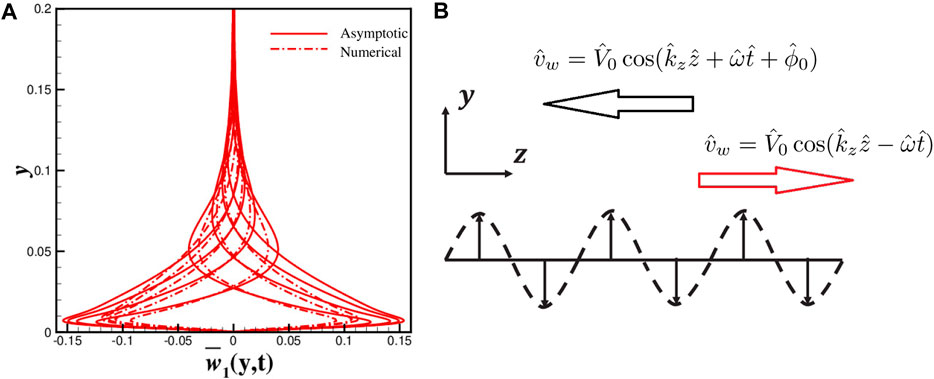
FIGURE 1. (A) Spanwise velocity w¯1y,t=0 from the numerical simulation (dash-dot line) and asymptotic solution (solid line, Eqs 8a-e) and (B) the sketch of the actuation.

To resolve the WBS induced flow in a quiescent background, an asymptotic expansion method is applied as shown in Eq. 4a–c:

w=w0+αw1+α2w2+Oα3(4a)
v=v0+αv1+α2v2+Oα3(4b)
p=p0+αp1+α2p2+Oα3(4c)

where α=V^0/c^, the ratio of the blowing and suction amplitude over the wave speed, is assumed as a small parameter, w0,v0,p0 are the zero-order terms, w1,v1,p1 are the first order terms, and w2,v2,p2 and higher order terms are not considered here. Without losing generality, the zero order terms are solved in the first half period t<ω^T^a as:

w0y,z,t=iH21HeyeHyeizt+c.c.(5a)
v0y,z,t=121HHey+eHyeizt+c.c.(5b)
H=1iβ=abi(5c)
a=12β2+1+1(5d)
b=12β2+11(5e)

where i=1 is the imaginary unit, and c.c. represents the complex conjugate. The Reynolds number β is based on the frequency ω^ and wave number k^z as:

β=ρ^ω^μ^k^z2(6)

The zero-order terms are a traveling wave in the same direction as actuation, which is also called the harmonic part in the manuscript. The harmonic part decays as the distance to the wall y increases, and the protrusion height is defined as δ^=0.73λ^z, where the amplitude of the velocity is only 1% of that at the wall.

The average of the first order terms is of much significance in this study:

w¯1y,t=limLLLw1y,z,tdz(7)

And it can be solved with known zero order terms (Eq. 5a, b):

w¯1y,t=n=1fnyexpinω0t+c.c.
fny=Cnexpinβω0y+fn,1y+fn,2y+fn,3y(8a)
fn,1y=21+ainγcosby21+absinby21+ainγ2+41+a2b2×b2aa2+1β2aa1inπ1n1e1+ay(8b)
fn,2y=21+ainγsinby+21+abcosby21+ainγ2+41+a2b2×b2a+1β2aa1inπ1n1e1+ay(8c)
fn,3y=b2a14a2inγinπβ1n1e2ay(8d)
γ=βω0,ω0=πωTa(8e)

where the constant Cn=fn,10+fn,20+fn,30 determined by the w¯1y,t=0 boundary condition at y = 0. This asymptotic solution matches the numerical results well with a slightly smaller amplitude, as shown in Figure 1A. The expression expinβω0yexpinω0t in Eqs 8a-e is the same as the Stokes layer with frequency nω0.In other words, the induced oscillatory spanwise motion w¯1y,t comprises a series of the Stokes layers with a frequency nπ/ω^T^a. Obviously, a large divergence exists between w¯1y,t and the Stokes layers within a very thin region above the wall as a result of different boundary conditions. The thickness of the first Stokes layer in the series (Eqs 8a-e), δs=4.62/ω0β or δ^sT^a with dimensions, is also regarded as the penetration height of the spanwise motion. The higher order terms in Eqs 8a-e, or the Stokes layers with multiple frequency nω0, are always neglected for analysis as their thickness is 1/n less and the amplitude is 1/n less. In the limit of ω^, the amplitude of w¯1y,t can be approximated by W^mV^02/8ν^ω^. When the frequency is zero, ω^=0, there is no average spanwise motion since the traveling wave degenerates to a constant blowing and suction. It is noticed that the relative error of asymptotic solutions is approximately less than 10% when the parameter α=V^0k^z/ω^ satisfies α<0.5. As a result, the oscillatory spanwise motion in Eqs 8a-e is called the Stokes part in the rest of the manuscript.

In summary, the motion induced by the spanwise traveling wave can be approximately decomposed into a harmonic part (Eq. 5a, b) and a Stokes part (Eqs 8a-e) with the asymptotic solution.

The Numerical Method and Base Flow

Incompressible fully developed turbulent channel flows with Reτ=uτh/ν180 (Reb=ρUbh/μ=2800) and Reτ=uτh/ν550 (Reb=ρUbh/μ=10000) are chosen as the base flow for control, where uτ=τw/ρ is the friction velocity and Ub is the bulk velocity of the channel. For the Reτ=180 channel flow, the computation domain is set as 0,2πh in streamwise (x) direction, 1,1 in wall-normal (y) direction, and 0,πh in spanwise (z) direction, with h the half channel height. In this study, u,v,w represents the velocities in x,y,z direction, respectively. The grid points are Nx×Ny×Ny=113×169×113 with a corresponding resolution x+10.1, z+5.0. Here, the “+” superscript represents inner-scale variables normalized by uτ and δv=ν/uτ. A hyperbolic tangent function y=tanhr2yi1/tanhr, yi=i1/Ny1 decides the grid distribution in wall-normal direction. The resolution 0.2<Δy+<5.2 is achieved with a stretch ratio r=2.4. And for the channel flow with Reτ=550, the computation domain is 0,3πh×1,1×0,2πh to resolve the large-scale structures [41, 42], with the resolution x+7.6, z+7.7, and 0.04<Δy+<2.9.

High order methods based on CPR(correction procedure via reconstruction) [43] are used here and seventh order polynomials are used for space discretization. For the viscous term, it is discretized with BR2 (the second approach of Bassi and Rebay) [44] and interior penalty method. The time advancement strategy is a third order explicity Euler scheme with a time step dt=1×10⁴ (dt+=dtuτ/δv0.00116). A constant flow rate (CFR) method is chosen in the computations of the channel flows. All the computations in this study are conducted with this type of direct numerical simulations (DNS).

The length and velocity scales are normalized by h and Ub in the turbulent channel flows without particular specification, respectively. Comparisons of our numerical results with those from Kim et al. [45](Reτ=180, and with those from Jiménez et al. [46](Reτ=550) in Reynolds stress of the uncontrolled channel flows is done firstly for verification of our computation code, which show a satisfying match in Figure 2. The vortex structures detected by Q-value also show a good match with previous work, see Figures 3A, B.

FIGURE 2
www.frontiersin.org

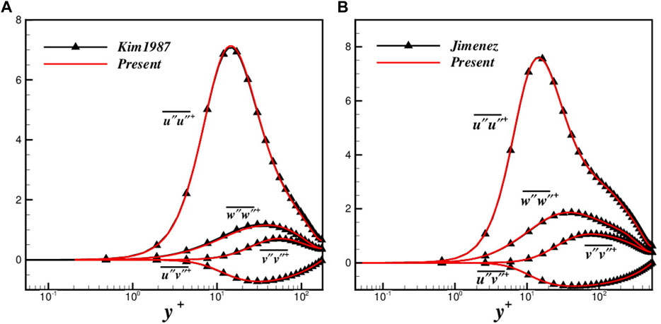
FIGURE 2. Comparison of Reynolds stress (A) between the present study and Kim et al. [45] with Reτ=180, and (B) between the present study and Jiménez et al. [46] with Reτ=550.

FIGURE 3
www.frontiersin.org

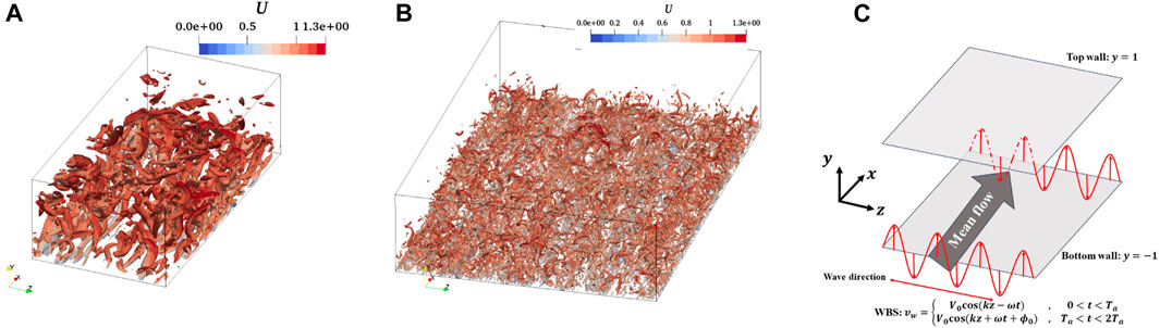
FIGURE 3. (A) Q iso-surface in Reτ=180, and (B) Reτ=550. (C) The sketch of WBS control strategy.

Results and Discussion

The spanwise traveling wave of blowing and suction control is imposed only at the bottom wall (y=1) of the channel flow with an uncontrolled upper wall (y=1), as shown in Figure 3C. In this section, the drag reduction performance of the WBS control is studied, and the drag reduction rate, noted as DR, is defined as:

DR=τw0τwτw0×100%,τw=1NxNyNtn=1Nti=1Nxk=1Nzμui,k,nyy=1(9)

where τw is the averaged skin friction of the bottom wall, and the subscript with ’0’ means the results in uncontrolled flow. The test cases in this manuscript are show in Table 1. In our previous work [15], it has been shown that the WBS control leads to a close drag reduction rate to the WOS control with the same parameter W,Ta. The drag reduction rates are much smaller with Reτ=550 than those with Reτ=180, while they have nearly the same optimal period Ta+60. Gatti et al. [22, 47] has shown the drag reduction rate dependence on Reynolds number DRReτ0.20.3, in WOS control. Obviously, the decrease in DR with increasing Reτ in WBS control is much larger.

TABLE 1
www.frontiersin.org

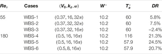
TABLE 1. The parameters and drag reduction rates of the test cases with W=V02/8νω.

FIK Identity Analysis

The variables in WBS control are decomposed into three parts:

ax,y,z,t=a¯y+ay,ϕ+ax,y,z,t=ay,ϕ+ax,y,z,t(10)

where a¯ is the ensemble average, ay,ϕ the phase average with ϕ representing the phase, and ax,y,z,t the turbulent fluctuations a=a¯a is the difference between the phase average and ensemble average, which is also called the periodic part. Fukagata, Iwamoto and Kasagi proposed an identity (known as FIK identity) relating the skin friction at the wall and the turbulent shear stress in the interior field. While in WBS control, it is rewritten as:

2CfbCfu=6RebCfL+3111yuv¯CfTdy+3111yuv¯dyCfP(11)

where CfL is the skin friction in uncontrolled flow, CfT the contribution from turbulent shear stress, and CfP the contribution from the shear stress formed by the periodic parts, respectively.

The turbulent skin friction part can be further decomposed into two parts [23, 24], one from the inner region (y+<yP+30) and the other from the outer region (y+>30), as shown in Eq. 12.

3111yuv¯dy=1yP1yuv¯dy+yP11yuv¯dy(12)

Therefore the drag reduction rate can be decomposed as shown in Eqs 13a-d:

2DR=DRI+DRO+DRP(13a)
DRI=1Cf031yP1yuv¯0uv¯dy(13b)
DRO=1Cf03yP11yuv¯0uv¯dy(13c)
DRP=1Cf03111yuv¯dy(13d)

where DRI, DRO, and DRP represents the drag reduction rate from the inner region, outer region, and periodic part, respectively. The factor “2” on the left-hand side of Eqs 13a-d comes from the one-side control in the channel flows. The drag reduction decomposition of the cases is shown in Table 2. The DR is mainly from DRI and DRO. DRP is always negative, which means the periodic blowing and suction has a negative effects to the drag reduction. On the other hand, compared to DRI and DRO, DRP is much smaller and even can be neglected when Reτ=180. While Reτ=550, the DRP becomes larger and even dominates in Case WBS-3. The strength of the oscillatory spanwise motion W+ is larger in Case WBS-3 compared to other cases with Reτ, but DR decreases a lot to a negative value. This means the negative effects of the periodic part on DR in this case become significant. The wavenumber increases from kz=8 (Case WBS-6) to kz=16 (Case WBS-5), the increases in DR are mainly from DRO, as a result of a smaller protrusion height δ=0.73λz. In addition, the DR gets smaller mainly from the decreases of DRO when Reτ increases, similar to the results in WOS control [23, 24].

TABLE 2
www.frontiersin.org

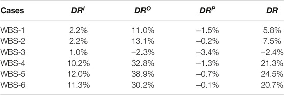
TABLE 2. Drag reduction decomposition of the cases.

The effects of DRP can be described by the lift-up mechanism from the harmonic parts of blowing and suction. Based on the asymptotic expansion (Eq. 4a–c), the streamwise velocity can be written as u=u0+αu1+α2u2+Oα3, and its equation is:

ux+αvuy+wwz=px+1Re2uy2+2uz2(14)

Since it is uniform in streamwise direction, there is no /x terms in the equation, and u can be solved with a known v,w. In addition, u0 is the prescribed baseflow and not dependent on v,w. Here, it is assumed that u0=Ky without losing generality, since the linear relation is always true in the linear law region [48]. Thus, the first order term u1 can be solved with v0,w0:

u1=KiH21HeyeHyRe4H1HyeHyexpizt+c.c.(15)

It is obvious that u1<0 above the blowing regions and u1>0 above the suction region, which is thought as a lift-up mechanism. Thus, there forms a negative shear stress uv, which is closely related to the CfP. Further, the spanwise average of the shear stress, noted as Sy, can be deduced:

Sy=limLz1Lz0Lzuvdz=S0y+αS1y+Oα2(16a)
S0y=0(16b)
S1y=limLz1Lz0Lzu1v0dz=K1a2+b2Sy1+Sy2(16c)
Sy1=a2+b2sinby+Recosby2absinby2a2+b2y+bcosby+asinby]e1+ay(16d)
Sy2=b+aRe2a2+b2ye2ay(16e)

In addition, the skin friction from the periodic part, CfP, can be evaluated as:

CfP3111ySydy3K111yαSyKV02dy(17)

As shown in Figure 4, the
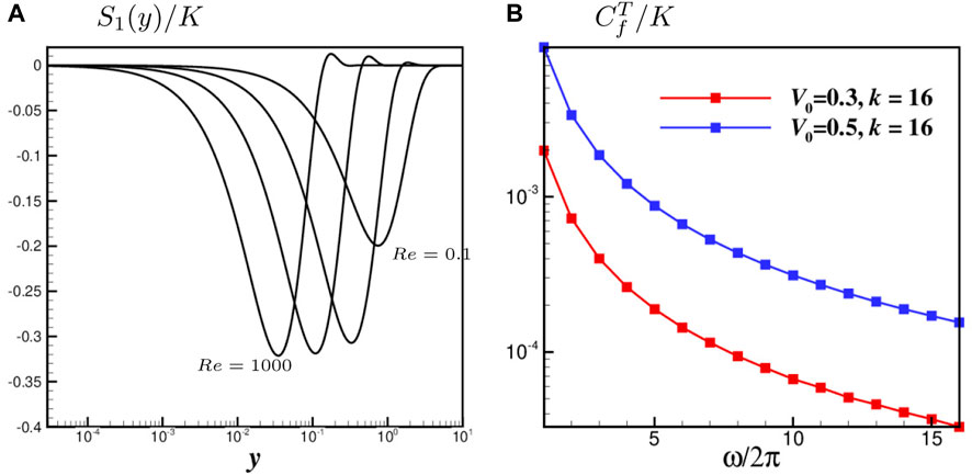
 Sy/K is always negative, leading to a positive CfP. As a result, the periodic parts always increase the skin friction, just as shown in Table 2. CfP decreases with an increasing frequency ω, which is also compliant with the results of Case WBS-2 and WBS-3. It is also found that CfPK, which means that the larger the shear K=U/y is in the background flow, the larger CfP is. When Reτ changes from 180 to 550, K increases and leads to a larger CfP, just as the results in Table 2.

FIGURE 4
www.frontiersin.org

FIGURE 4. (A) S1y/K with different Reynolds number and (B) CfP/K variation with different frequency ω.

As discussed in Control Strategy section, the induced flow by the traveling wave of blowing and suction with a periodically reversed wave speed can be decomposed into two parts, one is the harmonic part (zero order terms) and the other is the Stokes part (first order terms). The harmonic part will induce a negative shear stress, as shown in Eq. 16c, and lead to a positive contribution the skin friction through CfP. An effective way to reduce CfP is increasing ω, while an increased ω will lead to a smaller strength W=V02/8νω of the Stokes part. Therefore, there should be an optimal frequency in the WBS control, which is not discussed in details in this manuscript. In addition, CfP becomes larger with an increasing mean flow shear u/y in the viscous sublayer when Reτ changes from 180 to 550. This is thought to be the first reason that the drag reduction rate is smaller in Reτ=550 cases.

Scale Separation Analysis

In this section, a Fourier expansion based on spanwise direction is imposed to the fluctuation field variables, u=κ=1u^κexpiκz+c.c. Thus the stress can be decomposed into different scales as:

uiuj¯=κ=1u^iκexpiκz+c.c.κ=1u^jκexpiκz+c.c.¯=κ=1u^iκu^jκ*¯(18)

where the superscript “*” represents the complex conjugate. As a result, the skin friction coefficient from the turbulent shear stress, CfT can be also decomposed:

CfT=3111yuv¯dy=κ=13111yuv¯κdyCfTκ(19)

Thus, the contribution from the scale λ=2π/κ to the turbulent skin friction is CfTκ. The pre-multiplied spectrum of turbulent shear stress, κuv¯κ, and the skin friction coefficients, κCfTκ, of Case WBS-5 with Reτ=180 and Case WBS-2 with Reτ=550 are shown in Figure 5. The skin friction of all scale structure decreases after control in Reτ=180 case, while that of the medium scale, 100<λ+<700, decreases in Reτ=550 case. In addition, the spectrum κuv¯κ gets reduced nearly in the whole region, y/h<1, while the spectrum gets reduced in the region y+<30. As the Reτ increases, the contribution to the skin friction in the outer region increases, while the spanwise motion mainly affects the inner region, so the drag reduction rate is smaller in Reτ=550 than that in Reτ=180, as shown in Figure 5. To further analyze the control effects on the structures with different scales, we use a cut-off wavelength to divide the whole scale into large-scale (noted as LS) and small-scale (noted as SS) structures. The cut-off wave length is chosen as λzc+=300, which separates the two local maximum in the pre-multiplied spectrum, that is:

u=κ=1uκ=κ<2π/λzcuκLS+κ>2π/λzcuκSS(20)

FIGURE 5
www.frontiersin.org

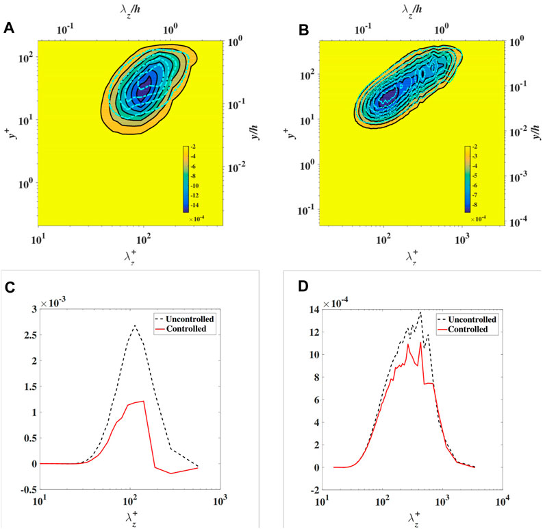
FIGURE 5. The pre-multiplied shear stress κuv¯κ in (A) Case WBS-5, and (B) Case WBS-2, and skin friction coefficients κCfTκ in (C) Case WBS-5, and (D) Case WBS-2. The dash-line represent the results in the uncontrolled case.

It was found that the vortex structures are inclined by the Stokes layers in WOS, which has a close relation to the drag reduction mechanism [14, 15, 1719]. In our previous analysis based on the Reτ=180 channel flow, the inclination is thought to be a representation of the stretch of the streamwise vortex, u/x. u/x gets reduced after control, leading to a weakened pressure-strain term ϕ11=pu/x¯. Thus, the energy transported into the wall-normal stress vv¯ from the streamwise stress uu¯ is reduced as a result of the incompressibility, ϕ11+ϕ22+ϕ33=0 [15]. Here we revisited the inclination of vortex structures in the controlled flow with Reτ=550. Figure 6 shows the streaks at y+11 in Case WBS-2 in one period. The inclination of the streaks is similar as that in Reτ=180 case. Also, the inclinations of streaks can be described by the inclinations of the two-point correlation, Cx,z, which is defined as:

Cx,z=ux,y,z,tux+x,y,z+z,t¯ux,y,z,tux,y,z,t¯(21)

FIGURE 6
www.frontiersin.org

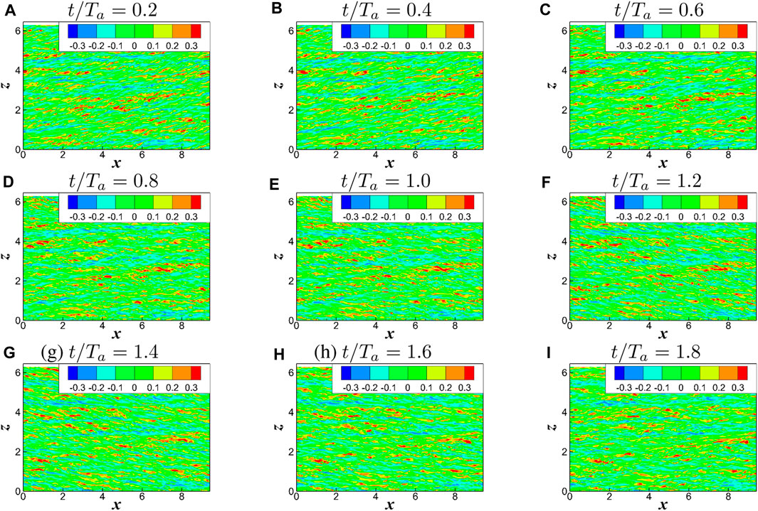
FIGURE 6. The streaks (u contour) at y+11 in Case WBS-2 with Reτ=550 at t/Ta = 0.2–1.8 in (A–I).

The contours of the streaks and Cx,z of SS and LS structures are shown in Figure 7. Thus, an inclination angle, noted as θ in radians, is defined as the angle between the axis of the iso-value line of Cx,z and the streamwise direction to give a quantitative description of the inclination of streaks. The angle θy,t of whole scales and separated scales (SS and LS) in Case WBS-2 are shown in Figure 8. It is shown that the angle θy,t has a phase difference at different wall distance y, which is induced by the spanwise motion [12, 14, 15]. The angle is largest at y+11, recalling that the spanwise motion affects the structures at this region most. Further for SS and LS structures, the angle of SS is nearly the same as all scale (AS) and much larger than that of LS. This tells us that the spanwise motion affects the SS structure more than the LS. In addition, the inclination of SS and LS structures has a phase delay.

FIGURE 7
www.frontiersin.org

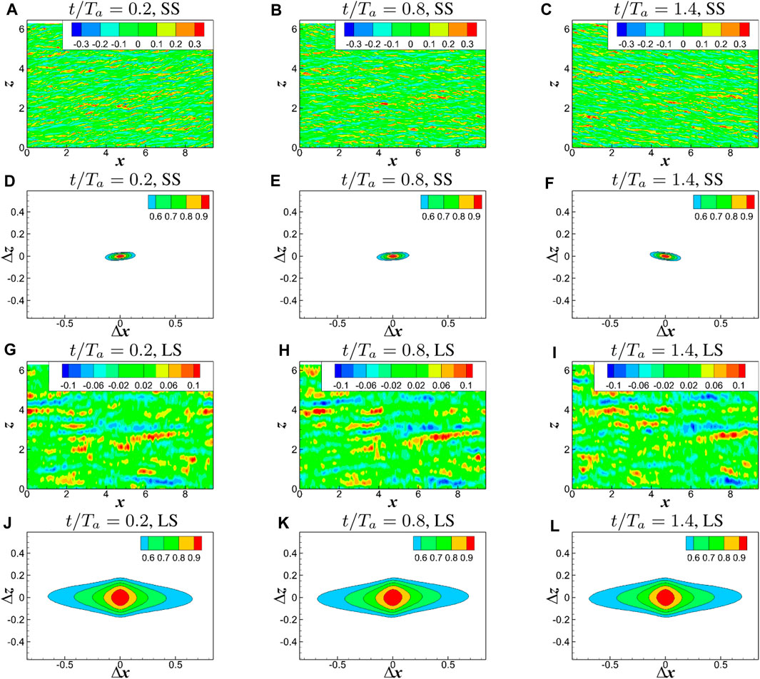
FIGURE 7. The streaks at y+=11 of SS structures (A–C) and LS structures (G–I), and two-point correlation Cx,z of SS structures (D–F) and LS structures (J–L).

FIGURE 8
www.frontiersin.org

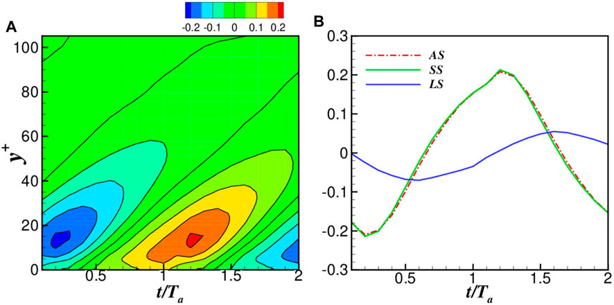
FIGURE 8. The angles (A) θy,t of whole scales and (B) θy+=11,t of LS, SS, and all-scale (AS).

In physical space, the oscillatory spanwise motion or the Stokes part mainly weakens the inner region (y+<30), as shown in Figure 5. When the Reτ gets larger with an increasing dominance of the outer region, the contribution from the inner region gets reduced, leading to a smaller drag reduction rate. In spectrum space, the Stokes part mainly affects the small-scale structures (λ+<300). While the Reτ gets larger, the large-scale structures become more significant, and the drag reduction is thus reduced.

Conclusion

In this study, the drag reduction performance of the spanwise traveling wave of blow and suction with a periodically reversing propagation direction in Reτ=180 and Reτ=550 turbulent channel flows is studied. An asymptotic expansion method is used to resolve the flow induced by this kind of actuation. The induced flow can be decomposed into the harmonic part (Oα0 terms) and the Stokes part (Oα1 terms), where the parameter α=V0/c is the ratio of amplitude of blowing and suction over the wavespeed of the traveling wave. The harmonic part will induce a negative shear stress, and thus increase the skin friction of the channel. However, it is always at a negligible level compared to the turbulent shear stress with a proper set of parameters, such as a large ω and low Reynolds number Reτ. The Stokes part, or oscillatory spanwise motion, can weaken the turbulence just as the wall oscillation control.

The drag reduction rates are much smaller in Reτ=550 cases that those in Reτ=180 cases. There are thought to be three reasons in this study. Firstly, the negative effects on the drag reduction rate from the harmonic part get larger in Reτ=550 cases. Secondly, the Stokes part can weaken the turbulence in the inner region, while the inner region becomes less dominant in high Reynolds number cases. Thirdly, the Stokes part mainly affect the small-scale structure, and similarly the small-scale structures are less dominant in high Reynolds number cases.

Data Availability Statement

The original contributions presented in the study are included in the article/supplementary material, further inquiries can be directed to the corresponding author.

Author Contributions

All authors listed have made a substantial, direct, and intellectual contribution to the work and approved it for publication.

Funding

China-EU Program: Drag Reduction via Turbulent Boundary Layer Flow Control (DRAGY), Grant agreement ID: 690623.

Conflict of Interest

The authors declare that the research was conducted in the absence of any commercial or financial relationships that could be construed as a potential conflict of interest.

References

1. Schrauf, G. Status and Perspectives of Laminar Flow. Aeronaut J (2005) 109(1102):639–44. doi:10.1017/s000192400000097x

CrossRef Full Text | Google Scholar

2. Ricco, P, and Lesshziner, MA. A Review of Turbulent Skin Friction Drag Reduction by Near Wall Transverse Forcing (2021). arXiv:2013.04719v1.

CrossRef Full Text | Google Scholar

3. Choi, H, Moin, P, and Moser, R. Direct Numerical Simulation of Turbulent Flow Over Riblets. J Fluid Mech (1993) 255:503–39. doi:10.1017/s0022112093002575

CrossRef Full Text | Google Scholar

4. Luchini, P, Manzo, F, and Pozzi, A. Resistance of a Grooved Surface to Parallel Flow and Cross-Flow. J Fluid Mech (1991) 228(228):87–109. doi:10.1017/s0022112091002641

CrossRef Full Text | Google Scholar

5. Bechert, DW, Bruse, M, Hage, JGT, Van Der Hoeven, W, and Hoppe, G. Experiments on Drag-Reducing Surfaces and Their Optimization With an Adjustable Geometry. J Fluid Mech (1997) 338:59–87. doi:10.1017/s0022112096004673

CrossRef Full Text | Google Scholar

6. Jung, WJ, Mangiavacchi, N, and Akhavan, R. Suppression of Turbulence in Wall-Bounded Flows by High-Frequency Spanwise Oscillations. Phys Fluids A: Fluid Dyn (1992) 4(8):1605–7. doi:10.1063/1.858381

CrossRef Full Text | Google Scholar

7. Quadrio, M, and Ricco, P. Initial Response of a Turbulent Channel Flow to Spanwise Oscillation of the Walls. J Turbulence (2003) 4(7):1–23. doi:10.1088/1468-5248/4/1/007

CrossRef Full Text | Google Scholar

8. Ricco, P, and Quadrio, M. Wall-Oscillation Conditions for Drag Reduction in Turbulent Channel Flow. Int J Heat Fluid Flow (2008) 29:891–902. doi:10.1016/j.ijheatfluidflow.2007.12.005

CrossRef Full Text | Google Scholar

9. Quadrio, M, and Ricco, P. Critical Assessment of Turbulent Drag Reduction Through Spanwise Wall Oscillations. J Fluid Mech (2004) 521:251–71. doi:10.1017/s0022112004001855

CrossRef Full Text | Google Scholar

10. Quadrio, M, Ricco, P, and Claudio, V. Streamwise-Traveling Waves of Spanwise Wall Velocity for Turbulent Drag Reduction. J Fluid Mech (2009) 627:161–78.

CrossRef Full Text | Google Scholar

11. Schlichting, H, and Gersten, K. Boundary Layer Theory. 9 edition. Springer (2016).

Google Scholar

12. Touber, E, and Leschziner, MA. Near-Wall Streak Modification by Spanwise Oscillatory Wall Motion and Drag-Reduction Mechanisms. J Fluid Mech (2012) 693(2):150–200. doi:10.1017/jfm.2011.507

CrossRef Full Text | Google Scholar

13. Ricco, P, Ottonelli, C, Hasegawa, Y, and Quadrio, M. Changes in Turbulent Dissipation in a Channel Flow With Oscillating Walls (2012). arXiv preprint arXiv:1202.3534.

CrossRef Full Text | Google Scholar

14. Agostini, L, Touber, E, and Leschziner, M. The Turbulence Vorticity as a Window to the Physics of Friction Drag Reduction by Oscillatory Wall Motion. Int J Heat Fluid Flow (2015) 51(3–15):3–15. doi:10.1016/j.ijheatfluidflow.2014.08.002

CrossRef Full Text | Google Scholar

15. Huang, Y, Wang, L, and Fu, S. Drag Reduction in Turbulent Channel Flows by a Spanwise Traveling Wave of Wall Blowing and Suction. Phys Fluids (2021) 33:095111. doi:10.1063/5.0061279

CrossRef Full Text | Google Scholar

16. Xu, C-X, and Huang, W-X. Transient Response of Reynolds Stress Transport to Spanwise Wall Oscillation in a Turbulent Channel Flow. Phys Fluids (2005) 17(1):018101. doi:10.1063/1.1827274

CrossRef Full Text | Google Scholar

17. Blesbois, O, Chernyshenko, SI, Touber, E, and Leschziner, MA. Pattern Prediction by Linear Analysis of Turbulent Flow With Drag Reduction by Wall Oscillation. J Fluid Mech (2013) 724:607–41. doi:10.1017/jfm.2013.165

CrossRef Full Text | Google Scholar

18. Choi, K-S. Near-Wall Structure of Turbulent Boundary Layer With Spanwise-Wall Oscillation. Phys Fluids (2002) 14(7):2530–42. doi:10.1063/1.1477922

CrossRef Full Text | Google Scholar

19. Chernyshenko, SI, and Baig, MF. The Mechanism of Streak Formation in Near-Wall Turbulence. J Fluid Mech (2005) 544:99–113. doi:10.1017/s0022112005006506

CrossRef Full Text | Google Scholar

20. Moarref, R, and Jovanovic, MR. Model-Based Design of Transverse Wall Oscillations for Turbulent Drag Reduction. J Fluid Mech (2012) 707:205–40. doi:10.1017/jfm.2012.272

CrossRef Full Text | Google Scholar

21. Yakeno, A, Hasegawa, Y, and Kasagi, N. Modification of Quasi-Streamwise Vortical Structure in a Drag-Reduced Turbulent Channel Flow With Spanwise Wall Oscillation. Phys Fluids (2014) 26(8):085109. doi:10.1063/1.4893903

CrossRef Full Text | Google Scholar

22. Gatti, D, and Quadrio, M. Performance Losses of Drag-Reducing Spanwise Forcing at Moderate Values of the Reynolds Number. Phys Fluids (2013) 25:125109. doi:10.1063/1.4849537

CrossRef Full Text | Google Scholar

23. Hurst, E, Yang, Q, and Chung, YM. The Effect of Reynolds Number on Turbulent Drag Reduction by Streamwise Travelling Waves. J Fluid Mech (2014) 759:28–55. doi:10.1017/jfm.2014.524

CrossRef Full Text | Google Scholar

24. Yao, J, Chen, X, and Hussain, F. Reynolds Number Effect on Drag Control via Spanwise Wall Oscillation in Turbulent Channel Flows. Phys Fluids (2019) 31:085108. doi:10.1063/1.5111651

CrossRef Full Text | Google Scholar

25. Agostini, L, and Leschziner, M. The Impact of Footprints of Large-Scale Outer Structures on the Near-Wall Layer in the Presence of Drag-Reducing Spanwise Wall Motion. Flow, Turbulence and Combustion (2018) 100:1037–61. doi:10.1007/s10494-018-9917-3

CrossRef Full Text | Google Scholar

26. Leschziner, MA. Friction-Drag Reduction by Transverse Wall Motion-A Review. J Mech (2020) 36:649–63.

CrossRef Full Text | Google Scholar

27. Ghebali, S, Chernyshenko, SI, and Leschziner, MA. Turbulent Skin-Friction Reduction by Wavy Surfaces (2017). arXiv preprint arXiv:1705.01989.

Google Scholar

28. Skote, M. Turbulent Boundary Layer Flow Subject to Streamwise Oscillation of Spanwise Wall-Velocity. Phys Fluids (2011) 23(8):081703. doi:10.1063/1.3626028

CrossRef Full Text | Google Scholar

29. Skote, M. Temporal and Spatial Transients in Turbulent Boundary Layer Flow Over an Oscillating Wall. Int J Heat Fluid Flow (2012) 38(1–12):1–12. doi:10.1016/j.ijheatfluidflow.2012.08.004

CrossRef Full Text | Google Scholar

30. Skote, M. Comparison Between Spatial and Temporal Wall Oscillations in Turbulent Boundary Layer Flows. J Fluid Mech (2013) 730:273–94. doi:10.1017/jfm.2013.344

CrossRef Full Text | Google Scholar

31. Wise, DJ, and Ricco, P. Turbulent Drag Reduction Through Oscillating Discs. J Fluid Mech (2014) 746(10):536–64. doi:10.1017/jfm.2014.122

CrossRef Full Text | Google Scholar

32. Wise, DJ, Alvarenga, C, and Ricco, P. Spinning Out of Control: Wall Turbulence Over Rotating Discs. Phys Fluids (2014) 26:125107. doi:10.1063/1.4903973

CrossRef Full Text | Google Scholar

33. Wise, DJ, Paolo, O, and Ricco, P. Turbulent Drag Reduction Through Oscillating Discs-Corrigendum. J Fluid Mech (2018) 856:1064–6.

CrossRef Full Text | Google Scholar

34. Jukes, T, Choi, K-S, Johnson, G, and Scott, S. Turbulent Drag Reduction by Surface Plasma Through Spanwise Flow Oscillation (2006).

Google Scholar

35. Jukes, T. Turbulent Drag Reduction Using Surface Plasma. PhD thesis. Nottingham: University of Nottingham (2007).

Google Scholar

36. Wilkinson, S. Oscillating Plasma for Turbulent Boundary Layer Drag Reduction. Int J Heat Fluid Flow (2012) 38(1–12).

Google Scholar

37. Xie, F, Pérez-Muñoz, JD, Ning, Q, and Pierre, R. Drag Reduction in Wall-Bounded Turbulence by Synthetic Jet Sheets. J Fluid Mech (2022) 941:A63. doi:10.1017/jfm.2022.347

CrossRef Full Text | Google Scholar

38. Min, T, Kang, SM, Speryer, JL, and Kim, J. Sustained Sub-Laminar Drag in a Fully Developed Channel Flow. J Fluid Mech (2006) 558:309. doi:10.1017/s0022112006000206

CrossRef Full Text | Google Scholar

39. Hœffner, J, and Fukagata, K. Pumping or Drag Reducion. J Fluid Mech (2009) 635:171–87. doi:10.1017/s0022112009007629

CrossRef Full Text | Google Scholar

40. Woodcock, JD, Sader, JE, and Marusic, I. Induced Flow Due to Blowing and Suction Flow Control: An Analysis of Transpiration. J Fluid Mech (2011) 690:366–98. doi:10.1017/jfm.2011.441

CrossRef Full Text | Google Scholar

41. Mathis, R, Hutchins, N, and Marusic, I. Large-Scale Amplitude Modulation of the Small-Scale Structures in Turbulent Boundary Layers. J Fluid Mech (2009) 628:311–37. doi:10.1017/s0022112009006946

CrossRef Full Text | Google Scholar

42. Mathis, R, Monty, JP, Hutchins, N, and Marusic, I. Comparison of Large-Scale Amplitude Modulation in Turbulent Boundary Layers, Pipes, and Channel Flows. Phys Fluids (2009) 21(11). doi:10.1063/1.3267726

CrossRef Full Text | Google Scholar

43. Shi, L, Wang, Z, Fu, S, and Zhang, L. A PnPm-CPR Method for Navier-Stokes Equations (2012).

Google Scholar

44. Bassi, F, and Rebay, S. Discontinuous Galerkin Solution of the Reynolds Averaged Navier-Stokes and K ω Turbulence Model Equations. J Comput Phys (2005) 34:507–40. doi:10.1016/j.compfluid.2003.08.004

CrossRef Full Text | Google Scholar

45. Kim, J, Moin, P, and Moser, R. Turbulence Statistics in Fully Developed Channel Flow at Low Reynolds Number. J Fluid Mech (1987) 177:133–66. doi:10.1017/s0022112087000892

CrossRef Full Text | Google Scholar

46. Jiménez, J. DNS Turbulent Channel Data (2016).

Google Scholar

47. Gatti, D, and Quadrio, M. Reynolds-Number Dependence of Turbulent Skin-Friction Drag Reduction Induced by Spanwise Forcing. J Fluid Mech (2016) 802:553–82. doi:10.1017/jfm.2016.485

CrossRef Full Text | Google Scholar

48. Pope, SB. Turbulent Flows. Cambridge University Press (2000).

Google Scholar

Keywords: drag reduction, turbulent channel flows, spanwise traveling wave, blowing and suction, Reynolds number dependence

Citation: Huang Y and Fu S (2024) Reynolds Number Effects on the Drag Reduction With a Spanwise Traveling Wave of Blowing and Suction in Turbulent Channel Flows. Aerosp. Res. Commun. 1:12272. doi: 10.3389/arc.2023.12272

Received: 22 October 2023; Accepted: 24 November 2023;
Published: 09 January 2024.

Copyright © 2024 Huang and Fu. This is an open-access article distributed under the terms of the Creative Commons Attribution License (CC BY). The use, distribution or reproduction in other forums is permitted, provided the original author(s) and the copyright owner(s) are credited and that the original publication in this journal is cited, in accordance with accepted academic practice. No use, distribution or reproduction is permitted which does not comply with these terms.

*Correspondence: Song Fu, fs-dem@tsinghua.edu.cn

Disclaimer: All claims expressed in this article are solely those of the authors and do not necessarily represent those of their affiliated organizations, or those of the publisher, the editors and the reviewers. Any product that may be evaluated in this article or claim that may be made by its manufacturer is not guaranteed or endorsed by the publisher.