Abstract
High-pressure swirling injection and combustion are important phenomena in a modern gas turbine engine as its compression ratio has been significantly increased to improve thermodynamic efficiency. Large eddy simulations are conducted to analyze turbulent flow and combustion of kerosene-air in a dual-air-swirler gas turbine model combustor at a supercritical pressure of 4 MPa, above the critical pressure of kerosene. The present work focuses particularly on effects of the two air swirler angles on flow and combustion dynamics. Numerical results indicate that the inner air swirler exerts strong impact on fuel-air mixing and chemical reactions inside the inner injector, leading to a Y shaped recirculating flow and a V shaped flame at an inner swirler angle of 40°. The precessing vortex core (PVC) is generated by the inner air swirling injection, and detailed analyses reveal that the PVC frequency is controlled mainly by the inner swirl number and the maximum axial velocity from the inner injector. The outer air swirler makes significant impact on the central recirculation structure and turbulent combustion inside the combustion chamber and weakly influences the PVC frequency. For the present supercritical-pressure turbulent combustion in a dual-air-swirler system, it appears that proper combination of the two air swirler angles could avoid chemical reactions deep inside the injector while enhancing fuel-air mixing and combustion in the combustion chamber.
Introduction
The modern gas turbine engine is an efficient and reliable power plant in the aviation system. The engine’s thermodynamic efficiency improves as its compression ratio increases, according to the principle of Brayton cycle [1]. As such, the overall pressure ratio in an advanced aero engine can now reach more than 40 and will be further increased [2]. This leads to supercritical-pressure combustion at high-thrust engine conditions, with the combustion chamber pressure above the fuel’s critical pressure, e.g., around 23 atm for the aviation kerosene.
In a gas turbine engine combustor, swirling air injection is generally used for enhancing fuel-air mixing and for flame holding [3, 4]. The swirling flow and turbulent combustion cause very complex physicochemical phenomena, including the central recirculation zone (CRZ), precessing vortex core (PVC), vortex breakdown, and flame flashback etc. [4–6]. These processes are influenced by many factors, such as the combustion chamber pressure, fuel-air equivalence ratio, swirler angle, and the inlet Reynolds number etc. [4, 6–8]. Among them, the swirler angle exerts a direct impact on flow and flame dynamics.
Many studies have been carried out to elucidate the effects of air swirlers on swirling flows and combustion in gas turbine engines. There are two different types of air swirlers, with axial or radial vanes, respectively. Huang et al. [9] investigated the effect of inlet swirling flow, with a single set of axial swirler vanes, on flame dynamics in a lean-premixed swirl-stabilized combustor, using the large eddy simulation (LES) technique. It was concluded that a large swirl number tends to increase the turbulence intensity and flame speed, resulting in the reduced flame surface area. Li et al. [10] used a similar set of axial air swirlers to study the swirling flow and combustion in a lean partially premixed combustor and analyzed the effects of swirl number, equivalence ratio, and nitrogen dilution on flame dynamics and NOx emissions. Aliyu et al. [11] conducted both experimental and numerical studies on oxy-combustion of the hydrogen-enriched methane in a swirl-stabilized gas turbine model combustor and discussed the effects of equivalence ratio, hydrogen concentration, and swirler angle on flame stability and temperature distribution. Jiang et al. [12] examined the effects of swirling flow and downstream wall confinement on the annular nonpremixed turbulent combustion, using the direct numerical simulation (DNS) approach. It was revealed that a large swirl number causes the reduced flame length and the increased flame spreading at the downstream location. Mansouri et al. [13] studied the turbulent premixed flame of propane in a lean-premixed swirl-stabilized burner and analyzed the effect of swirling intensity on flame behaviors. It was observed that a largely increased swirl number leads to flame flashback.
Besides a single set of swirlers, the multiple sets of air swirlers are also applied in a practical combustion system. This causes interactions of swirling flows from different sets of air swirlers and makes the combustion process more complicated [14]. Wang et al. [15] studied the influence of inlet swirling intensity on the vortical flow dynamics in a gas turbine injector with three sets of radial-entry and counter-rotating swirl vanes. It was found that the increased swirling velocity could enhance unsteady motion in the azimuthal direction and would suppress the development of streamwise instability in the outer shear layer. Further studies on the effects of multiple sets of swirler interactions on fuel-air mixing and combustion are still needed.
As the combustion chamber pressure increases in a modern aero engine and becomes higher than the critical pressure of the hydrocarbon engine fuel, the surface tension of the fuel significantly decreases, and its heat of vaporization vanishes. Thereby, the fuel-air injection and combustion processes are controlled by direct turbulent mixing, with large variations of thermophysical properties [16–18]. This is very different from the physicochemical processes of fuel spray, atomization, droplet vaporization, and turbulent combustion at low chamber pressures.
A number of experimental studies have been conducted to gain fundamental understanding on supercritical-pressure combustion, almost entirely in liquid-propellant rocket engines. Habiballah et al. [19] studied the liquid oxygen (LOx) and hydrogen combustion at a subcritical pressure of 3.0 MPa and a supercritical pressure of 6.0 MPa. It was revealed that the combustion rate is strongly dependent on the droplet vaporization rate at the low pressure, but it is controlled by the turbulent mixing rate at the high pressure. Juniper et al. [20] and Candel et al. [21] analyzed the LOx-hydrogen flame structures in coaxial injection and combustion at a supercritical pressure of 7.0 MPa. Singla et al. [22] examined the LOx-methane flames at both subcritical and supercritical inlet temperatures under a supercritical pressure. Many numerical studies were also carried out to obtain deep insights on flow and flame dynamics at high pressures in rocket engine systems [23–26]. However, very few studies on swirling flow and turbulent combustion in the gas turbine combustor at supercritical pressures have been conducted in the literature [8, 27].
A supercritical-pressure turbulent combustion model has recently been presented, validated, and applied for studying the effects of different chamber pressures and fuel-air equivalence ratios on swirling flow and combustion in a gas turbine model combustor [8]. Based on this numerical model, large eddy simulations are further conducted in this paper to study the effects of dual air swirlers on turbulent flow and combustion dynamics of kerosene-air in a dual-air-swirler gas turbine model combustor at a supercritical pressure of 4 MPa, which is higher than the critical pressure of kerosene. The operation condition is closely related to the high-thrust operation of a modern aero engine. The present studies analyze the interactions of two sets of swirling air injection, with varied swirler angles, on fuel-air mixing and turbulent combustion at a supercritical pressure.
Numerical Model and Model Validations
A supercritical-pressure turbulent flow and combustion model was previously developed, with consideration of the general-fluid effect [8] and based on the flamelet progress-variable (FPV) approach [28]. This model is applied in the present numerical study. The Favre-filtered conservation equations of mass, momentum, mixture fraction, mixture fraction variance, and progress variable, which are solved in the numerical model, are presented in Equations 1–5.where is the filtered density, the Favre-filtered velocity, the filtered pressure, the viscosity, the subgrid-scale (SGS) turbulent viscosity, the strain rate tensor, the 3 × 3 identity tensor, the Favre-filtered mixture fraction, the SGS mixture fraction variance, the Favre-filtered progress variable, the thermal diffusivity, the SGS turbulent diffusivity, the reaction rate of progress variable, and Δ the filter width. The progress variable, C, is defined as the sum of mass fractions of CO, CO2, H2, and H2O. The model constants, Sct and Cχ, are chosen as 0.9 and 2.0, respectively.
It should be noted that the simulated combustion system in the present study is assumed to be adiabatic, neglecting the radiative and convective heat losses. The previous numerical simulations [29, 30] indicated that these heat losses have essentially no effect on flow and flame structures.
The Smagorinsky model [31] is used to calculate the SGS turbulent viscosity.In Equations 6, 7, LS is the mixing length, κ the von Kármán constant (0.40), d the distance to the closest wall, and fμ the wall damping function. The model constant is chosen as CS = 0.17 in the present work.
In the FPV model, laminar counterflow flames are calculated using the flamelet equations, with proper account of the large thermodynamic and transport property variations, as described in the following paragraph. The flamelet databases are then pre-generated, using the presumed shape PDFs, to obtain the thermochemical quantities in the turbulent flow field, including the Favre-filtered temperature, Favre-filtered mass fractions of chemical species etc.In Equations 8, 9, is the presumed joint PDF, and represents a thermochemical quantity calculated from the laminar flames.
In the FPV model and flamelet calculations, large thermophysical property variations, particularly in the trans-critical region when the temperature of kerosene rises from the subcritical to supercritical state under a pressure above its critical value, are evaluated using the extended corresponding states (ECS) method, along with a BWR equation of state for a reference fluid, propane. More details concerning the ECS method can be found in the previous publications [32, 33]. A three-component surrogate model, which consists of 74% n-decane, 15% n-propylbenzene, and 11% n-propylcyclohexane in volume, is used to represent the aviation kerosene. A detailed chemical reaction mechanism, containing 209 species and 1,673 elementary reactions, is applied to handle chemical reactions [34, 35].
The conservation equations of , , and Equations 3–5, are built into the CFD software package, Fluent, through its user-defined scalars (UDSs), and the pre-generated flamelet databases are implemented using the user-defined functions (UDFs).
Model validations have been conducted in the prior publications [8, 36] regarding different cases of turbulent combustion, including the swirling and co-axial ones, at both low- and high-pressure conditions. For the readers’ convenience, the results are further presented in this paper.
In the first validation case, large eddy simulations were carried out to study the partially premixed turbulent combustion of methane-air in a dual swirl model combustor at the atmospheric pressure [37], using a detailed chemical reaction mechanism from GRI-MECH 2.11 with 49 chemical species and 277 elementary reactions [38]. As shown in Figure 1, comparisons of numerical and experimental results, including the time-averaged temperature, axial velocity, and tangential velocity etc., demonstrate that both the flame shape and flow structures can be well predicted, with the averaged relative quantitative error within 15% [8].
FIGURE 1
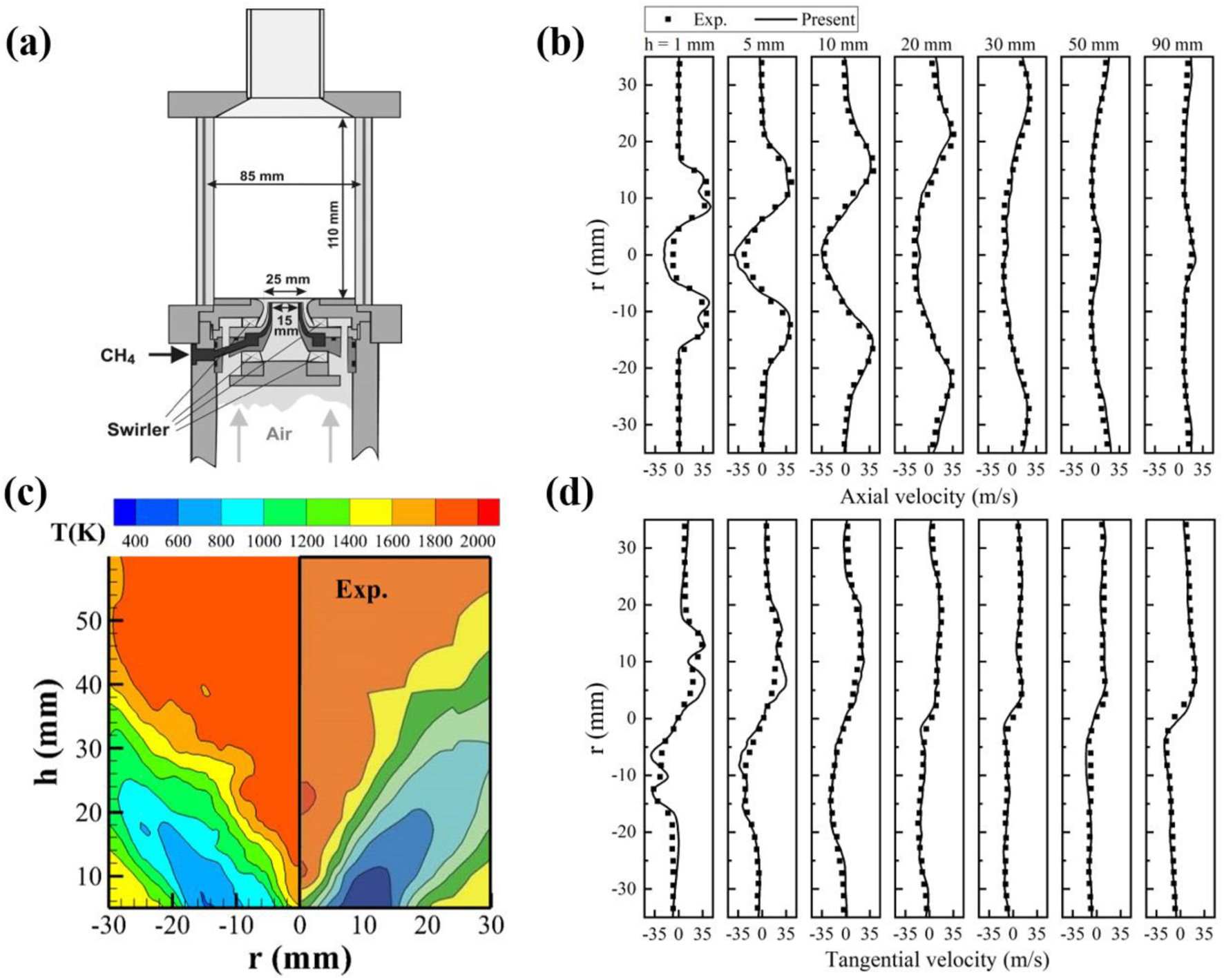
Model validations in a dual-swirl model combustor (A); Comparisons of the axial velocity variations (B), the temperature distributions (C), and the tangential velocity variations (D).
In the second validation case, which concerns turbulent combustion of the trans-critical liquid oxygen (LOx) and supercritical methane in a model rocket combustor at a high pressure of 5.6 MPa [22, 39], large eddy simulations were again conducted using GRI-MECH 2.11. As shown in Figure 2, comparisons of the time-averaged OH mass fraction and the instantaneous temperature variation between the experimental and numerical results indicate that the shape and length of the turbulent flame can also be properly predicted at high pressure conditions [8].
FIGURE 2
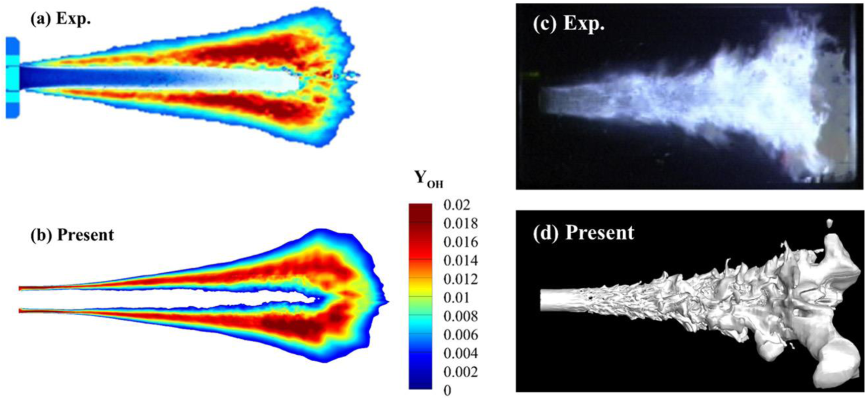
Model validations at a high pressure; comparisons of the time-averaged OH mass fraction (A, B) and the instantaneous iso-temperature surface (C, D).
More validation cases can also be found in Refs [36, 40], calculated using the similar turbulent combustion model. These validation results are not repeated in this paper.
Results and Discussion
Large eddy simulations are carried out in this work to study swirling injection and turbulent combustion of kerosene-air in a dual-swirl gas turbine model combustor at a supercritical pressure of 4 MPa, focusing on the effects of varied dual air swirler angles on the turbulent flow and combustion processes.
Figure 3A shows the schematic of the combustion system, which is chosen and slightly modified from the work by Chrigui et al. [41, 42]. It consists of a cylindrical combustion chamber, with 150 mm in length and 96 mm in diameter, and a contracted exit section, with 40 mm in diameter. Figure 3B illustrates the injection system, which contains two radial air swirlers and a fuel nozzle. The inner air swirler has a circular exit with a diameter of 16.04 mm, while the outer air swirler has an annular exit with diameters of 16.44 and 23.55 mm, respectively. The inner and outer swirlers include 8 and 12 radial gas channels, respectively, with the same rotation direction and similar rectangular cross section. The mean exit angles of the inner and outer swirlers are defined by α and β, respectively, as shown in Figure 3B. The fuel nozzle is 1 mm in diameter, through which the aviation kerosene is rotationally injected into the inner air stream. The other relevant parameters are provided in Table 1 and can also be found in the references [8, 41, 42].
FIGURE 3
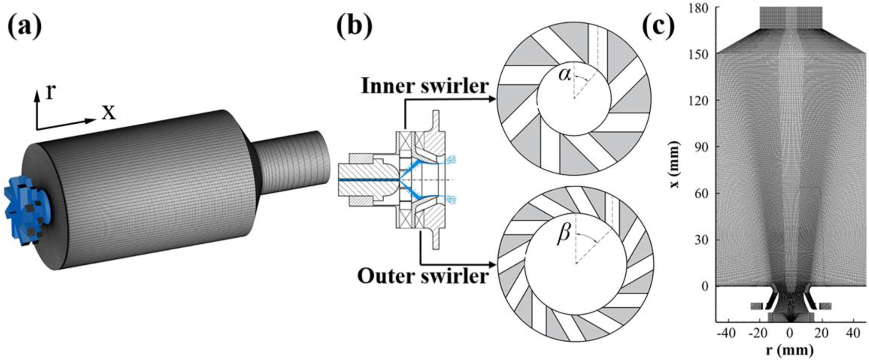
Schematics of the model combustor (A) and the injection system (B); Illustration of the computational meshes (C).
TABLE 1
| Inner swirler angle α (°) | 25, 40 |
| Outer swirler angle β (°) | 45 |
| Chamber pressure (MPa) | 4 |
| Kerosene inlet temp. (K) | 300 |
| Air inlet temp. (K) | 860 |
| Kerosene density (kg/m3) | 765.7 |
| Air density (kg/m3) | 15.85 |
| Kerosene mass flow rate (g/s) | 17.964 |
| Inner air mass flow rate (g/s) | 141.44 |
| Outer air mass flow rate (g/s) | 212.16 |
| Total equivalence ratio ϕ | 0.75 |
Parameters used in numerical calculations.
Based on the prior grid-independence study [8, 27], a set of computational meshes of 4.4 million hexahedral cells, which are sufficiently refined in the injector and flame regions, are used in the present large eddy simulations. Figure 3C shows the computational grids in the mid-plane of the combustor. The M value in Equation 10, as proposed by Pope et al. [43], are calculated to evaluate the mesh quality.where k is the directly resolved turbulent kinetic energy, and ksgs the turbulent kinetic energy in the sub-grid scale. It was found that the M value is less than 0.2 in the combustor and less than 0.3 in the majority of the air injector, except in some small regions near the wall at the inlets. Therefore, the present computational grids are sufficient for LES studies.
In the following calculations, the velocity-inlet and pressure-outlet boundary conditions are applied, and the no-slip and adiabatic boundary conditions are specified at all the walls. The computational time step is specified at 0.5 μs to ensure the maximum CFL number less than 1.0. The statistical results are collected after 10 flow-through time with over 30 ms.
Effect of the Inner Air Swirler Angle
The effect of the inner air swirler angle on fuel-air mixing and turbulent combustion is first studied. Two cases, with the inner swirler angle (α) varied from 25° to 40° and the outer swirler angle (β) fixed at 45°, are calculated and compared. The fuel, kerosene, is injected at a temperature of 300 K, while the air is at an increased temperature of 860 K, due to the compression-related heating. The overall fuel-air equivalence ratio is maintained at a lean condition of 0.75. Detailed parameters are provided in Table 1.
Figure 4 shows the time-averaged axial velocity variations. At an inner swirler angle of 25°, the central recirculation zone (CRZ) exists only in the combustion chamber with a U shape. As the swirler angle increases to 40°, however, the central recirculation zone extends upstream inside the inner injector to form a Y shape.
FIGURE 4
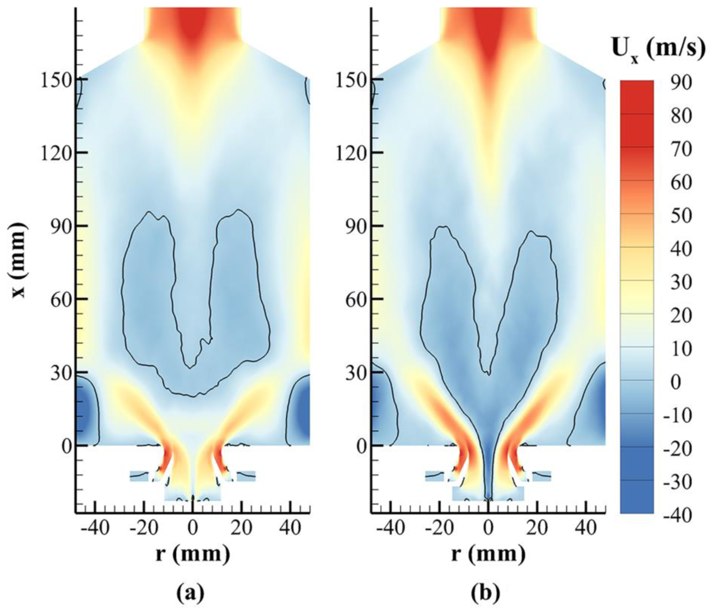
Variations of the time-averaged axial velocity at different inner swirler angles (the black line denotes the location at zero velocity). (A) α = 25°. (B) α = 40°.
The CRZ is caused by the axial variation of pressure gradient from swirling flows. In the present cases, the following relationship can be obtained [44, 45]:where R is the radius of the vortex core, a the ratio of the radial and axial velocity ur/ux, and Γ the magnitude of circulation by the tangential velocity ut. The item on the left-hand side is the pressure gradient at the combustor central axis. From Equation 11, the pressure gradient is dictated mainly by the magnitude of circulation Γ.
Figure 5 illustrates variations of the instantaneous tangential velocity and flow streamlines. It can be observed that as the inner air swirler angle increases from 25° to 40°, the tangential velocity and thus the circulation in the inner injector and upstream region of the combustor increase significantly, thereby resulting in a large pressure gradient along the axial direction, according to Equation 11. A positive pressure gradient is generated near the injector exit and the upstream region of the combustor, because of the positive radial velocity, ur, from flow expansion into the combustor. Therefore, at an inner swirler angle of 40°, the large adverse pressure variation results in strong reverse flows, both in the upstream region of the combustor and inside the inner injector.
FIGURE 5
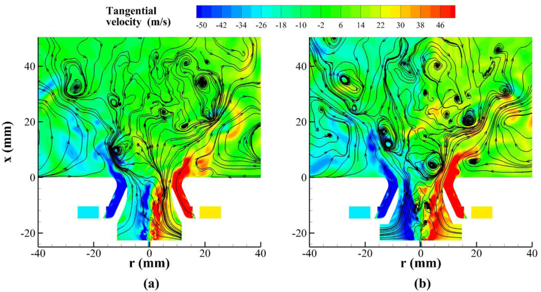
Distributions of the instantaneous tangential velocity and flow streamlines at different inner swirler angles (β = 45°). (A) α = 25°. (B) α = 40°.
In the downstream region of the combustor, under the combined effects of swirling flow and exit contraction (corresponding to the negative ur), a large negative pressure gradient is generated in the axial direction, which causes flow acceleration and a bifurcated structure of the CRZ [45], as evidenced in Figure 4. This phenomenon is mainly controlled by the outer swirler angle, as discussed in the next section.
Table 2 presents the swirl numbers in the inner and outer injectors, calculated based on the velocities at x = −3.64 mm (the coordinate system is shown in Figure 3, with x = 0 defined at the injector exit). The swirl number is defined as [36, 37].where Gt is the axial flux of the angular momentum, Gx the axial flux of the axial momentum, Ri the inner radius, and Ro the outer radius.
TABLE 2
| Inner swirler angle (α) | 25° | 40° |
|---|---|---|
| Inner swirl number S | 0.448 | 0.556 |
| Inner Gt (kg∙m2/s2) | 0.00365 | 0.00623 |
| Inner Gx (kg∙m/s2) | 1.01 | 1.40 |
| Outer swirl number S | 0.937 | 0.936 |
| Outer Gt (kg∙m2/s2) | 0.0243 | 0.0243 |
| Outer Gx (kg∙m/s2) | 2.20 | 2.20 |
The calculated swirl numbers at different inner swirler angles (β = 45°).
Results in Table 2 reveal that both Gt and Gx in the inner injector increase as the inner swirler angle changes from 25° to 40°. The increase of Gx is owing to the increased axial velocity near the inner injector wall, as shown in Figure 4, while the increase of Gt is caused by the enhanced tangential velocity, as shown in Figure 5. The increase of Gt is relatively larger and thus leads to a higher inner swirl number at α = 40°. The Gt and Gx in the outer injector remain almost the same for the two cases.
The swirling flow strongly influences turbulent combustion. Figure 6 shows the time-averaged temperature variations. At an inner swirler angle of α = 40°, the strong recirculating flow inside the inner injector, as shown in Figures 4B, 5B, promotes fuel-air mixing and also carries the hot combustion products back into the injector to ignite the fuel-air mixture. Therefore, in this case, combustion occurs inside the inner injector. In the case at α = 25°, however, combustion and the flame exist mainly at the injector exit.
FIGURE 6
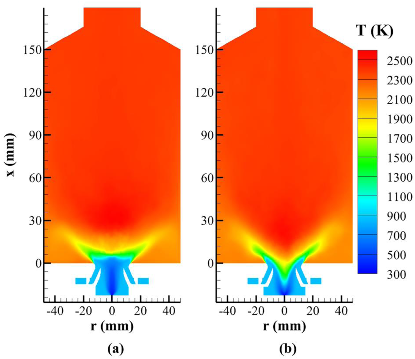
Variations of the time-averaged temperature at different inner swirler angles (β = 45°). (A) α = 25°. (B) α = 40°.
The effect of the inner air swirler angle on turbulent combustion can also be observed in Figure 7, which shows variations of the instantaneous reaction rate of the progress variable. At α = 40°, the flame exhibits a V shape inside the injector. As the inner swirler angle decreases to α = 25°, however, the flame moves to the injector exit, consistent with the temperature variations in Figure 6. In this case (α = 25°), chemical reactions occur mainly in a partially premixed mode, because of the partial fuel-air mixing inside the inner injector. This can be confirmed by analyzing the normalized flame index (NFI) [8, 24].
FIGURE 7
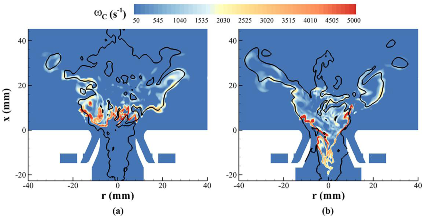
Distributions of the instantaneous reaction rate of the progress variable at different inner swirler angles (the black line denotes the location of the stoichiometric mixture fraction Zst = 0.0634). (A) α = 25°. (B) α = 40°.
At α = 40°, the temperature rise from combustion inside the inner injector would cause fuel pyrolysis, as shown in Figure 8, which presents distributions of the instantaneous mass fractions of the light-weight species of methane and ethylene. It can be seen that these two chemical components are mainly produced in the fuel-rich regions. Since the alkenes and aromatics from fuel pyrolysis are coking precursors, they could cause carbon deposition on the injector interior surface. Therefore, it appears that a large inner air swirler angle should be avoided under conditions of the present high-pressure turbulent combustion.
FIGURE 8
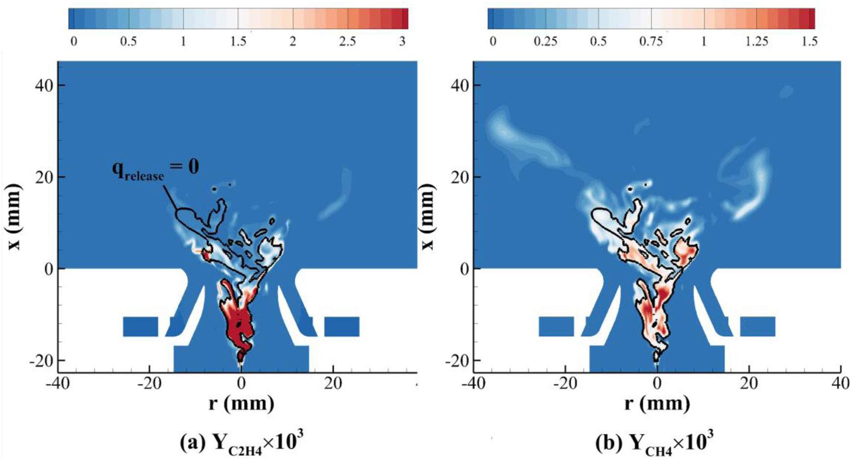
Distributions of the instantaneous species mass fractions of (A) methane and (B) ethylene at α = 40° (the black line denotes the location where the heat release rate from combustion is zero).
In the two cases, strong swirling flow would generate the precessing vortex core (PVC), which originates inside the inner injector. Figure 9 illustrates the PVC in the case at α = 40° [8]. Variations of the instantaneous radial velocity are also monitored at a location in the combustor with x = 11 mm and r = 12 mm (the coordinate system is shown in Figure 3, with x = 0 defined at the injector exit). Fast Fourier transformation (FFT) is further performed to obtain the velocity spectrum, as shown in Figure 10. The main PVC frequency, f, is found to increase from 994 to 1736 Hz, as the inner air swirler angle increases from 25° to 40°.
FIGURE 9
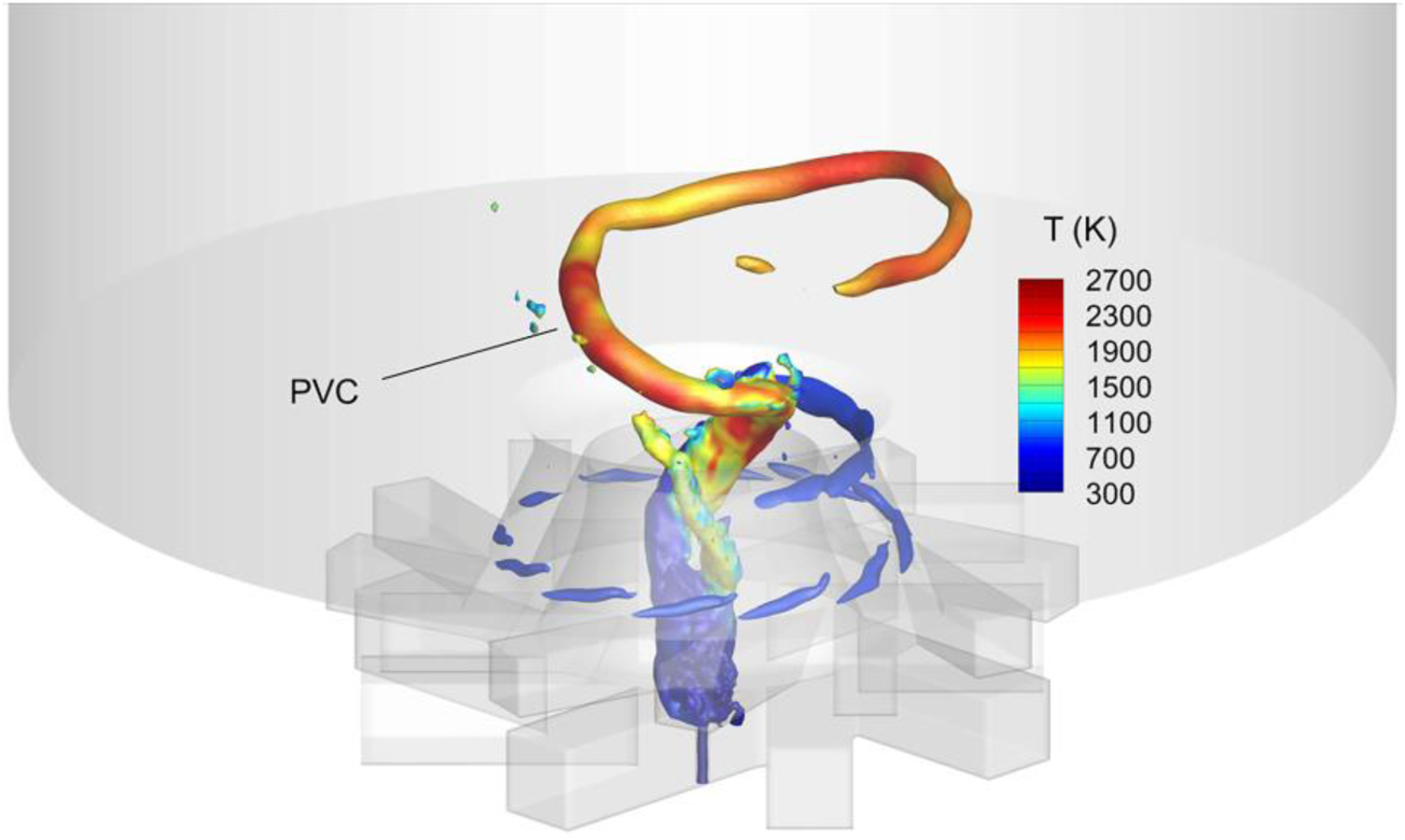
Illustration of the PVC at α = 40° (isobaric surface colored by temperature) [8].
FIGURE 10
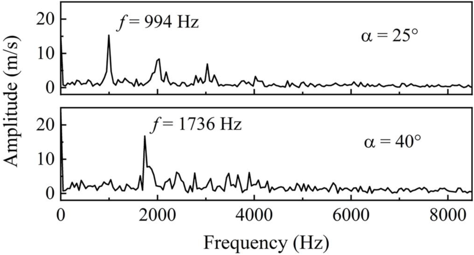
PVC frequency variations at different inner swirler angles (β = 45°).
In an isothermal flow, a Strouhal number, Sr, can be introduced to characterize the PVC frequency [6].where is the diameter at the injector exit, and the average injection velocity. Previous studies have confirmed that the Strouhal number is a function of swirl number, and therefore, the PVC frequency increases quasi-linearly with the flowrate at a fixed swirl number.
In the present combustion cases, density variation from chemical heat release significantly influences fluid flows. As a result, the Strouhal number defined with a bulk velocity in Equation 13 is found to be inaccurate. Therefore, a modified Strouhal number, , is proposed in the present study.In Equation 14, dinner is the inner injector diameter, the maximum axial velocity in the inner injector, e.g., the first peaks shown in Figure 11 (the second peak velocity in Figure 11 is caused by the outer air injector). The choice of is reasonable in the present combustion cases, because its location corresponds to the region where the helical PVC is generated in the inner injector.
FIGURE 11
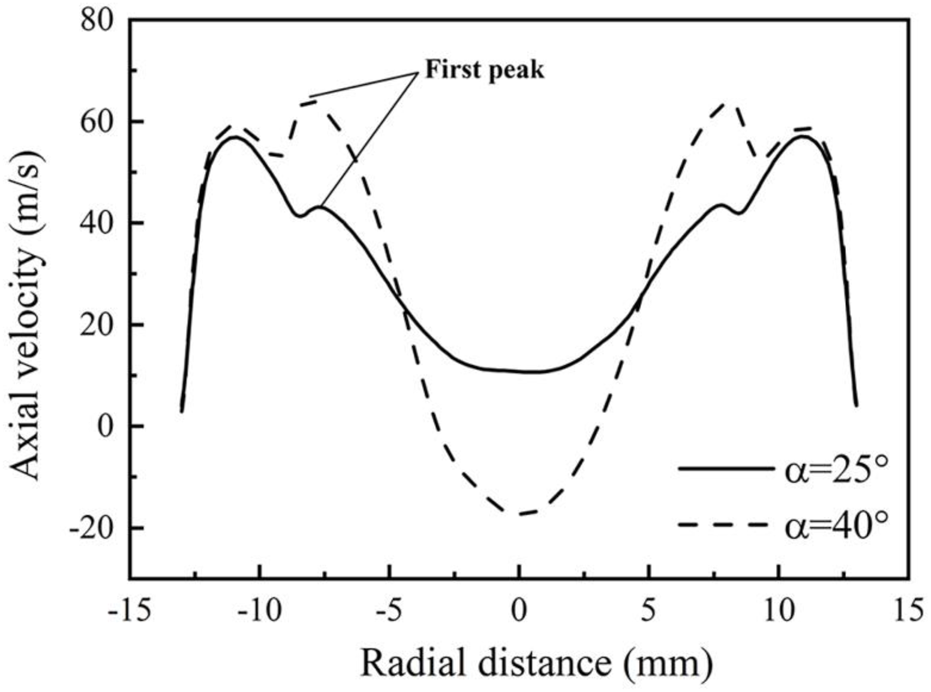
Radial variations of the axial velocity at the injector exit (β = 45°).
Calculations show that the modified Strouhal number, , is also controlled mainly by the inner swirl number, confirmed by the following relationship:
As presented in Table 3, the calculated parameter, SC, remains essentially a constant at around 0.8 for the two cases, with a relative difference less than 5%. This indicates that in the present combustion cases, the PVC frequency depends mainly on the inner swirl number and the maximum axial velocity in the inner injector. Therefore, the increased PVC frequency at a larger inner swirler angle of α = 40° results from the combined effects of the increased inner swirl number and the flow acceleration in the inner injector, as listed in Table 3. These two parameters are further influenced by the interactions of reverse flow and chemical reactions in the inner injector.
TABLE 3
| Inner swirler angle (α) | 25° | 40° |
|---|---|---|
| Inner swirl number | 0.448 | 0.556 |
| Maximum axial velocity (m/s) | 43.5 | 63.8 |
| PVC frequency (Hz) | 994 | 1736 |
| 0.366 | 0.435 | |
| SC | 0.816 | 0.783 |
The modified Strouhal numbers and PVC frequencies at different inner swirler angles (β = 45°).
Effect of the Outer Air Swirler Angle
The effect of the outer air swirler angles on turbulent flow and combustion is next examined. In the following calculations, the outer air swirler angle varies from β = 30°–45°, while the inner swirler angle is first set at α = 40° but later changed to 25° for further parametric studies. The other parameters remain the same as those in Effect of the Inner Air Swirler Angle section.
Figures 12A, B show the time-averaged axial velocity distributions at α = 40°, with two different β angles of 30° and 45°. For both cases, strong recirculation flows exist inside the combustor and the inner injector. As discussed in the preceding section, the recirculation flow inside the inner injector is controlled mainly by the inner air swirler angle. The CRZ in the combustor changes to a bubble shape, instead of a Y shape, as the outer swirler angle decreases from 45° to 30°. Therefore, it shows that flow acceleration in the downstream region of the combustor, which controls the bifurcated CRZ structure, is strongly influenced by the outer swirler angle.
FIGURE 12
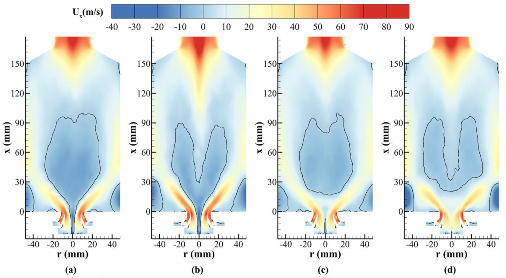
Variations of the time-averaged axial velocity at different inner and outer swirler angles (the black line denotes the location at zero velocity). (A) α = 40°, β = 30°. (B) α = 40°, β = 45°. (C) α = 25°, β = 30°. (D) α = 25°, β = 45°.
The downstream flow acceleration is driven by the axial pressure gradient, which depends strongly on the magnitude of circulation Γ, as shown in Equation 11. Figure 13 presents the radial variations of the tangential velocity at different axial locations at α = 40°. It can be clearly observed that as the outer swirler angle decreases to β = 30°, the tangential velocity is evidently reduced in the downstream region, consistent with the weakened flow acceleration towards the combustor exit, as shown in Figure 12A.
FIGURE 13
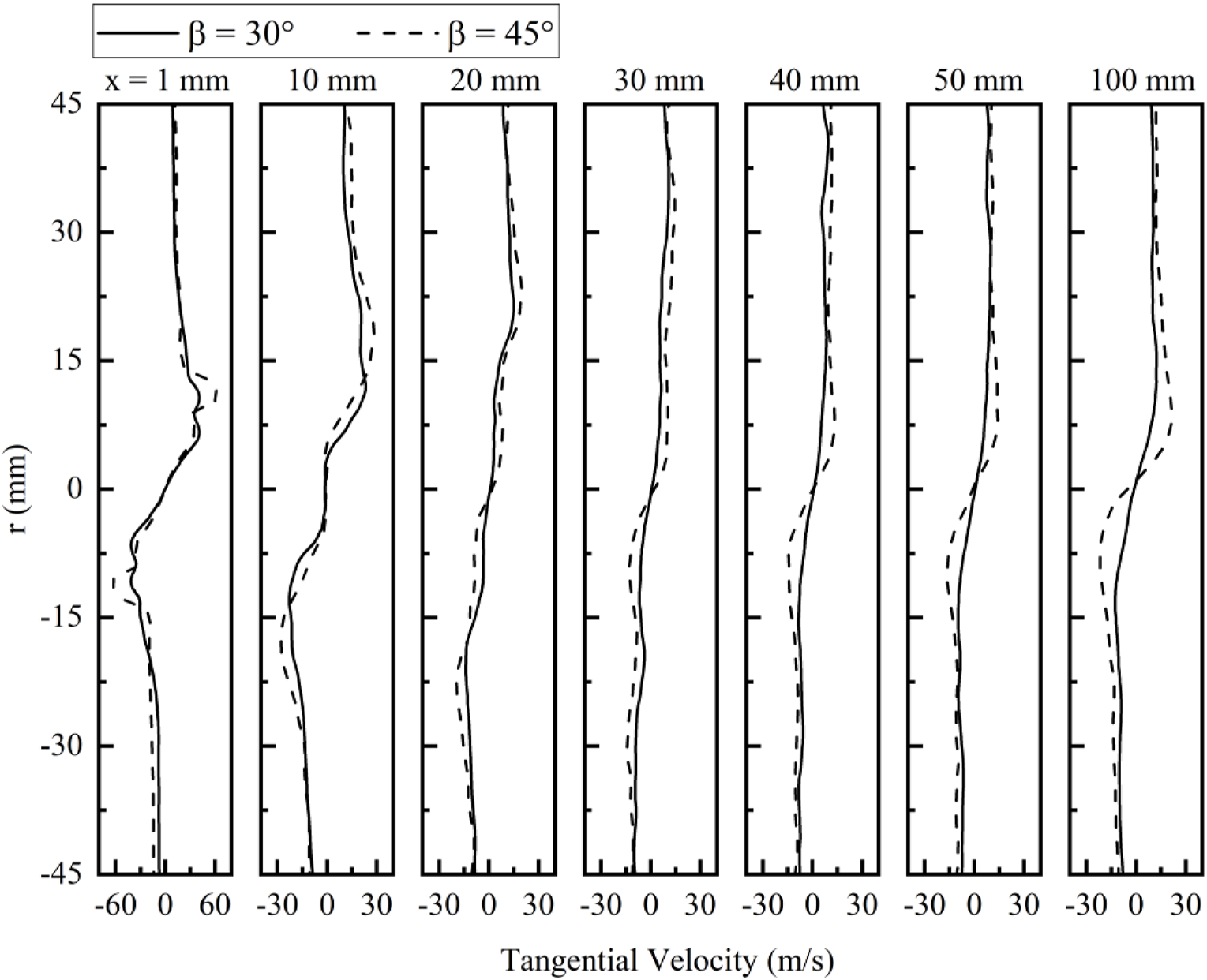
Radial variations of the time-averaged tangential velocity at two different outer swirler angles (α = 40°).
Table 4 presents the inner and outer swirl numbers at different cases, calculated based on the velocities at x = −3.64 mm, using Equation 12. The outer swirl number significantly increases as the outer swirler angle varies from β = 30°–45°. However, it is interesting to notice that at α = 40°, the inner swirl number slightly decreases, around 10%, as the outer swirler angle increases. This is related to the interactions of the swirling flow and turbulent combustion. Figure 14 shows the time-averaged temperature variations at two different outer swirler angles. The high-temperature flame exists inside the inner injector in both cases, but at a larger outer swirler angle of β = 45°, chemical reactions occur relatively deeper inside the inner injector. The resulting gas expansion and flow acceleration increase the outflow axial velocity but reduce the tangential velocity near the inner injector wall.
TABLE 4
| Inner swirler angle (α) | 40° | 25° | ||
|---|---|---|---|---|
| Outer swirler angle (β) | 30° | 45° | 30° | 45° |
| Inner swirl number S | 0.613 | 0.556 | 0.449 | 0.448 |
| Inner Gt (kg∙m2/s2) | 0.00652 | 0.00623 | 0.00375 | 0.00365 |
| Inner Gx (kg∙m/s2) | 1.33 | 1.40 | 1.04 | 1.01 |
| Outer swirl number S | 0.674 | 0.936 | 0.686 | 0.937 |
| Outer Gt (kg∙m2/s2) | 0.0151 | 0.0243 | 0.0153 | 0.0243 |
| Outer Gx (kg∙m/s2) | 1.90 | 2.20 | 1.89 | 2.20 |
The calculated swirl numbers at different inner and outer swirler angles.
FIGURE 14
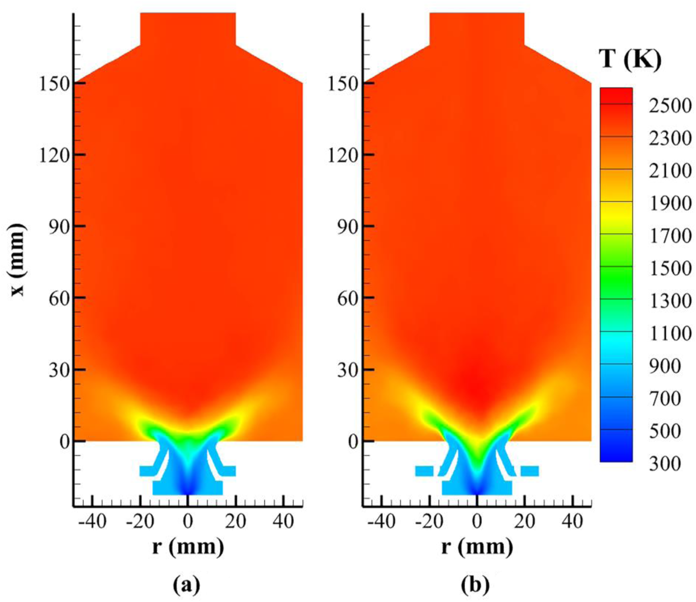
Distributions of the time-averaged temperature at different outer swirler angles (α = 40°). (A) β = 30°. (B) β = 45°.
Figures 15A, B present distributions of the instantaneous reaction rate of the progress variable at α = 40°. It is confirmed that turbulent flame exists inside the inner injector in both cases, but the flame moves toward the injector exit at a decreased outer swirler angle of β = 30°. Therefore, it appears that the outer swirler angle can also exert influence on the swirling flow and turbulent combustion inside the inner injector, mainly through its effect on the recirculating flow and CRZ in the combustor.
FIGURE 15
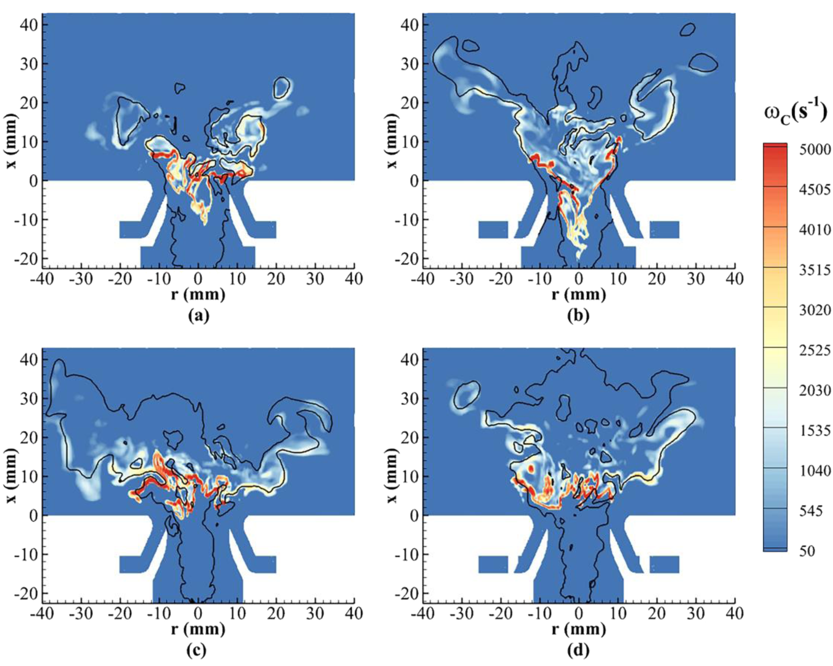
Distributions of the instantaneous reaction rate of progress variable at different inner and outer swirler angles (the black line denotes the location of the stoichiometric mixture fraction Zst = 0.0634). (A) α = 40°, β = 30°. (B) α = 40°, β = 45°. (C) α = 25°, β = 30°. (D) α = 25°, β = 45°.
As listed in Table 5, at a larger inner swirler angle of α = 40°, the outer swirler angle makes essentially no effect on the PVC frequency. The constant PVC frequency in the two cases at α = 40° is due to a balance between the slightly decreased inner swirl number and the slightly increased maximum axial velocity as the outer swirler angle increases. The parameter, SC, as defined in Equation 15, is also calculated and listed in Table 5. Again, it is essentially a constant in the two cases, with a relative difference less than 5%.
TABLE 5
| Inner swirler angle (α) | 40° | 25° | ||
|---|---|---|---|---|
| Outer swirler angle (β) | 30° | 45° | 30° | 45° |
| Inner swirl number | 0.613 | 0.556 | 0.449 | 0.448 |
| Maximum axial velocity (m/s) | 60.6 | 63.8 | 52.1 | 43.5 |
| PVC frequency (Hz) | 1763 | 1736 | 1,189 | 994 |
| 0.465 | 0.435 | 0.354 | 0.366 | |
| SC | 0.759 | 0.783 | 0.813 | 0.816 |
The modified Strouhal numbers and PVC frequencies at different inner and outer swirler angles.
The effect of the outer air swirler angle, varied from β = 30°–45°, on fluid flow and turbulent combustion is further studied at an inner swirler angle of α = 25°, with all the other parameters being the same.
Numerical results in Figures 12C, D clearly confirm that decreasing the inner air swirler angle to α = 25° would prohibit reverse flow and thus avoid chemical reactions inside the inner injector, at the two different outer swirler angles. Therefore, this would be a good choice for both thermally protecting the injector and largely reducing carbon deposition on its interior surface.
Results in Figures 12C, D also reveal that at α = 25°, as the outer air swirler angle rises from β = 30°–45°, the CRZ in the combustor changes from a bubble shape to a U shape, indicating again the strong impact of the outer swirler angle on the central recirculating flow in the combustor.
The swirl numbers for the two cases at α = 25° are also calculated and provided in Table 4. As previously observed, the outer swirl number significantly increases as the outer swirler angle rises to β = 45°. This would help enhance fuel-air mixing and swirling combustion at the injector exit and in the combustion chamber, as shown in Figure 15D. In these two cases, the outer swirler angle exerts essentially no effect on the inner swirl number, mainly because no reverse flow and combustion takes place inside the inner injector at a moderate inner swirler angle of α = 25°.
The PVC frequency variations in the two cases at α = 25° are shown in Figure 16. In these cases, the main PVC frequency slightly decreases, from 1,189 to 994 Hz, as the outer swirler angle increases from β = 30° to 45°. According to Equation 15, this is due mainly to the decreased maximum axial velocity in the inner injector, as listed in Table 5. It should be emphasized that the parameter, SC, remains essentially a constant in all of the four cases calculated in Table 5. The maximum relative error is within 7%.
FIGURE 16
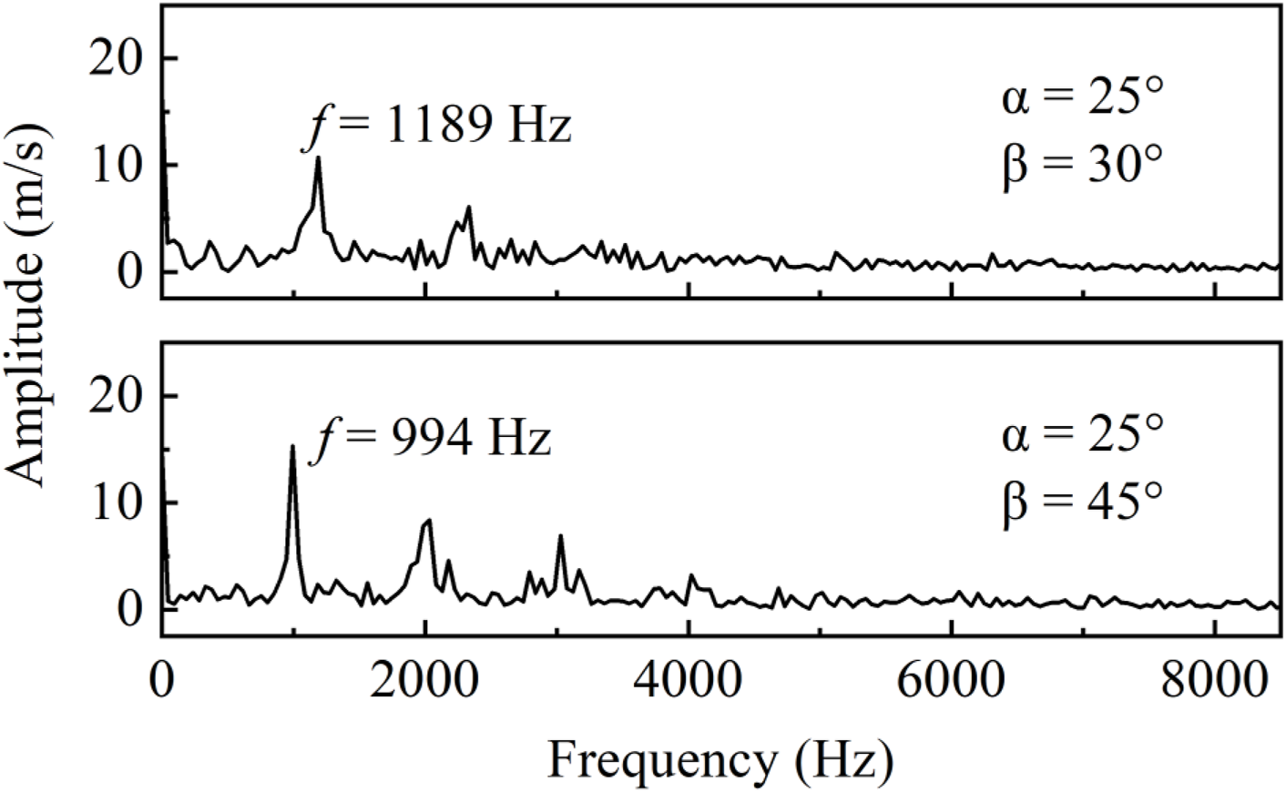
PVC frequency variations at different outer swirler angles (α = 25°).
Conclusion
Large eddy simulations are conducted to study swirling injection and turbulent combustion of kerosene-air in a dual-air-swirler gas turbine model combustor at a supercritical pressure of 4 MPa, which is above the critical pressure of the kerosene (at around 23 atm). The phenomena are closely related to practical operations of an advanced aero engine at high-thrust conditions. As a sequel to a previous study concerning the effects of different chamber pressures and equivalence ratios, the present studies focus on the effects of two air swirler angles on flow dynamics, fuel-air mixing, and combustion characteristics.
Results indicate that the inner air swirler exerts strong impact on fluid flow and turbulent combustion inside the inner injector. An increased inner air swirler angle would cause reverse flow and combustion in the inner injector, leading to a Y shaped recirculating flow and a V shaped flame. The precessing vortex core (PVC) is generated in the inner injector, and its frequency is significantly influenced by the inner air swirler angle, increasing from 994 to 1,736 Hz as the swirler angle varies from 25° to 40°. According to a modified Strouhal number proposed in this work, the PVC frequency is controlled mainly by two parameters, the inner swirl number and the maximum axial velocity in the inner injector. The PVC frequency increases as the maximum axial velocity or the inner swirl number increases.
The outer air swirler exerts strong impacts on recirculating flow and turbulent combustion in the combustion chamber. As the outer swirler angle rises from 30° to 45°, the central recirculation zone (CRZ) changes from a bubble shape to a U or Y shape, depending on different inner air swirler angles. The outer air swirler can also make weak influence on the swirling flow in the inner injector and the PVC frequency, mainly through its strong effect on the CRZ in the combustor. The PVC frequency decreases from 1,189 to 994 Hz as the outer swirler angle increases from 30° to 45°, at an inner swirler angle of 25°.
According to the present numerical results, it appears that for supercritical-pressure combustion in a dual-air-swirler gas turbine combustor, a moderate inner air swirler angle, e.g., between 25° and 40°, should be applied to reduce reverse flow and avoid chemical reactions deep inside the inner injector. A relatively large outer air swirler angle, e.g., at around 45°, should be used to help enhance swirling flow and combustion at the injector exit and inside the combustion chamber.
Statements
Data availability statement
The original contributions presented in the study are included in the article/supplementary material, further inquiries can be directed to the corresponding author.
Author contributions
DW conducted model validations, numerical calculations, data analyses, and manuscript drafting; DH developed the computational code, conduct model validations and numerical calculations; JX helped with coding, model validations, and data analyses; HM proposed the research topic, guided the research process, and finalized the manuscript.
Funding
The author(s) declare that financial support was received for the research, authorship, and/or publication of this article. This work is supported by the specialized research projects of Huanjiang Laboratory of Zhejiang Province.
Conflict of interest
The authors declare that the research was conducted in the absence of any commercial or financial relationships that could be construed as a potential conflict of interest.
Generative AI statement
The author(s) declare that no Generative AI was used in the creation of this manuscript.
References
1.
Saravanamuttoo HIH Rogers GFC Cohen H . Gas Turbine Theory. London, England: Pearson Education (2001).
2.
Epstein AH . Aircraft Engines’ Needs From Combustion Science and Engineering. Combust Flame (2012) 159(5):1791–2. 10.1016/j.combustflame.2012.02.022
3.
Lefebvre AH . Gas Turbine Combustion. Boca Raton, Florida: CRC Press (1998).
4.
Candel S Durox D Schuller T Bourgouin J-F Moeck JP . Dynamics of Swirling Flames. Annu Rev Fluid Mech (2014) 46:147–73. 10.1146/annurev-fluid-010313-141300
5.
Arndt CM Dem C Meier W . Influence of Fuel Staging on Thermo-Acoustic Oscillations in a Premixed Stratified Dual-Swirl Gas Turbine Model Combustor. Flow Turbul Combust (2021) 106:613–29. 10.1007/s10494-020-00158-6
6.
Syred N . A Review of Oscillation Mechanisms and the Role of the Precessing Vortex Core (PVC) in Swirl Combustion Systems. Prog Energ Combust Sci (2006) 32(2):93–161. 10.1016/j.pecs.2005.10.002
7.
Gicquel LYM Staffelbach G Poinsot T . Large Eddy Simulations of Gaseous Flames in Gas Turbine Combustion Chambers. Prog Energ Combust Sci (2012) 38(6):782–817. 10.1016/j.pecs.2012.04.004
8.
Huang D Xu J Chen R Meng H . Large Eddy Simulations of Turbulent Combustion of Kerosene-Air in a Dual Swirl Gas Turbine Model Combustor at High Pressures. Fuel (2020) 282:118820. 10.1016/j.fuel.2020.118820
9.
Huang Y Yang V . Effect of Swirl on Combustion Dynamics in a Lean-Premixed Swirl-Stabilized Combustor. Proc Combust Inst (2005) 30(2):1775–82. 10.1016/j.proci.2004.08.237
10.
Li S Zheng Y Zhu M Martinez DM Jiang X . Large-Eddy Simulation of Flow and Combustion Dynamics in a Lean Partially Premixed Swirling Combustor. J Energ Inst (2017) 90(1):120–31. 10.1016/j.joei.2015.09.004
11.
Aliyu M Nemitallah MA Said SA Habib MA . Characteristics of H2-Enriched CH4-O2 Diffusion Flames in a Swirl-Stabilized Gas Turbine Combustor: Experimental and Numerical Study. Int J Hydrog Energ (2016) 41(44):20418–32. 10.1016/j.ijhydene.2016.08.144
12.
Jiang X Luo KH De Goey LPH Bastiaans RJM Van Oijen JA . Swirling and Impinging Effects in an Annular Nonpremixed Jet Flame. Flow Turbul Combust (2011) 86(1):63–88. 10.1007/s10494-010-9287-y
13.
Mansouri Z Aouissi M Boushaki T . A Numerical Study of Swirl Effects on the Flow and Flame Dynamics in a Lean Premixed Combustor. Int J Heat Technol (2016) 34(2):227–35. 10.18280/ijht.340211
14.
Vashahi F Rezaei S Dafsari RA Lee J . Sensitivity Analysis of the Vane Length and Passage Width for a Radial Type Swirler Employed in a Triple Swirler Configuration. Theor Appl Mech Lett (2019) 9(6):363–75. 10.1016/j.taml.2019.05.004
15.
Wang S Hsieh S-Y Yang V . Unsteady Flow Evolution in Swirl Injector with Radial Entry. I. Stationary Conditions. Phys Fluids (2005) 17(4):045106. 10.1063/1.1874892
16.
Bellan J . Supercritical (And Subcritical) Fluid Behavior and Modeling: Drops, Streams, Shear and Mixing Layers, Jets and Sprays. Prog Energ Combust Sci (2000) 26(4-6):329–66. 10.1016/S0360-1285(00)00008-3
17.
Yang V . Modeling of Supercritical Vaporization, Mixing, and Combustion Processes in Liquid-Fueled Propulsion Systems. Proc Combust Inst (2000) 28(1):925–42. 10.1016/S0082-0784(00)80299-4
18.
Oefelein JC . Thermophysical Characteristics of Shear-Coaxial LOX-H2 Flames at Supercritical Pressure. Proc Combust Inst (2005) 30(2):2929–37. 10.1016/j.proci.2004.08.212
19.
Habiballah M Orain M Grisch F Vingert L Gicquel P . Experimental Studies of High-Pressure Cryogenic Flames on the Mascotte Facility. Combust Sci Technol (2006) 178(1-3):101–28. 10.1080/00102200500294486
20.
Juniper M Tripathi A Scouflaire P Rolon J-C Candel S . Structure of Cryogenic Flames at Elevated Pressures. Proc Combust Inst (2000) 28(1):1103–9. 10.1016/S0082-0784(00)80320-3
21.
Candel S Juniper M Singla G Scouflaire P Rolon C . Structure and Dynamics of Cryogenic Flames at Supercritical Pressure. Combust Sci Technol (2006) 178(1-3):161–92. 10.1080/00102200500292530
22.
Singla G Scouflaire P Rolon C Candel S . Transcritical Oxygen/Transcritical or Supercritical Methane Combustion. Proc Combust Inst (2005) 30(2):2921–8. 10.1016/j.proci.2004.08.063
23.
Masquelet M Menon S Jin Y Friedrich R . Simulation of Unsteady Combustion in a LOX-GH2 Fueled Rocket Engine. Aerosp Sci Technol (2009) 13(8):466–74. 10.1016/j.ast.2009.07.005
24.
Kang J Sung H-G . Kerosene/GOx Dynamic Combustion Characteristics in a Mixing Layer Under Supercritical Conditions Using the LES-FPV Approach. Fuel (2017) 203:579–90. 10.1016/j.fuel.2017.04.088
25.
Wang X Liu T Ma D Yang V . Linear Stability of Real-Fluid Mixing Layers at Supercritical Pressures. Phys Fluids (2022) 34(8):084106. 10.1063/5.0101342
26.
Zhang L Wang X Li Y Yeh S-T Yang V . Supercritical Fluid Flow Dynamics and Mixing in Gas-Centered Liquid-Swirl Coaxial Injectors. Phys Fluids (2018) 30(7):075106. 10.1063/1.5026786
27.
Huang D Wang D Xu J Meng H . Computational Study of the Effect of Dual Air Swirling Injection on Turbulent Combustion of Kerosene–Air at a High Pressure. Eng Proc (2023) 56(1):274. 10.3390/ASEC2023-15265
28.
Pierce CD Moin P . Progress-Variable Approach for Large-Eddy Simulation of Non-Premixed Turbulent Combustion. J Fluid Mech (2004) 504:73–97. 10.1017/s0022112004008213
29.
Gövert S Mira D Kok JBW Vázquez M Houzeaux G . The Effect of Partial Premixing and Heat Loss on the Reacting Flow Field Prediction of a Swirl Stabilized Gas Turbine Model Combustor. Flow Turbul Combust (2018) 100:503–34. 10.1007/s10494-017-9848-4
30.
Donini A Bastiaans RJM van Oijen JA de Goey LPH . A 5-D Implementation of FGM for the Large Eddy Simulation of a Stratified Swirled Flame With Heat Loss in a Gas Turbine Combustor. Flow Turbul Combust (2017) 98(3):887–922. 10.1007/s10494-016-9777-7
31.
Smagorinsky J . General Circulation Experiments With the Primitive Equations: I. The Basic Experiment. Mon Weather Rev (1963) 91(3):99–164. 10.1175/1520-0493(1963)091<0099:GCEWTP>2.3.CO;2
32.
Meng H Yang V . A Unified Treatment of General Fluid Thermodynamics and Its Application to a Preconditioning Scheme. J Comput Phys (2003) 189(1):277–304. 10.1016/S0021-9991(03)00211-0
33.
Xu K Meng H . Analyses of Surrogate Models for Calculating Thermophysical Properties of Aviation Kerosene RP-3 at Supercritical Pressures. Sci China Technol Sci (2015) 58(3):510–8. 10.1007/s11431-014-5752-5
34.
Dagaut P Cathonnet M . The Ignition, Oxidation, and Combustion of Kerosene: A Review of Experimental and Kinetic Modeling. Prog Energ Combust Sci (2006) 32(1):48–92. 10.1016/j.pecs.2005.10.003
35.
Dagaut P El Bakali A Ristori A . The Combustion of Kerosene: Experimental Results and Kinetic Modelling Using 1- to 3-Component Surrogate Model Fuels. Fuel (2006) 85(7-8):944–56. 10.1016/j.fuel.2005.10.008
36.
Huang D Wang Q Meng H . Modeling of Supercritical-Pressure Turbulent Combustion of Hydrocarbon Fuels Using a Modified Flamelet-Progress-Variable Approach. Appl Therm Eng (2017) 119:472–80. 10.1016/j.applthermaleng.2017.03.088
37.
Weigand P Meier W Duan XR Stricker W Aigner M . Investigations of Swirl Flames in a Gas Turbine Model Combustor: I. Flow Field, Structures, Temperature, and Species Distributions. Combust Flame (2006) 144(1-2):205–24. 10.1016/j.combustflame.2005.07.010
38.
Bowman CT Hanson RK Davidson DF Gardiner JWC Lissianski V Smith GP et al (1995). Available from: http://combustion.berkeley.edu/gri-mech/new21/version21/text21.html (Accessed September 15, 2018).
39.
Kim T Kim Y Kim S-K . Effects of Pressure and Inlet Temperature on Coaxial Gaseous Methane/Liquid Oxygen Turbulent Jet Flame Under Transcritical Conditions. J Supercrit Fluids (2013) 81:164–74. 10.1016/j.supflu.2013.05.011
40.
Xu J Huang D Chen R Meng H . An Improved NO Prediction Model for Large Eddy Simulation of Turbulent Combustion. Flow Turbul Combust (2020) 106(3):881–99. 10.1007/s10494-020-00204-3
41.
Chrigui M Sadiki A Janicka J Hage M Dreizler A . Experimental and Numerical Analysis of Spray Dispersion and Evaporation in a Combustion Chamber. At Sprays (2009) 19(10):929–55. 10.1615/AtomizSpr.v19.i10.30
42.
Chrigui M . N-Heptane Spray Evaporation and Dispersion in Turbulent Flow Within a Complex Geometry Configuration. Comput Therm Sci Int J (2010) 2(1):55–78. 10.1615/ComputThermalScien.v2.i1.50
43.
Pope SB . Ten Questions Concerning the Large-Eddy Simulation of Turbulent Flows. New J Phys (2004) 6(1):35. 10.1088/1367-2630/6/1/035
44.
Hall MG . Vortex Breakdown. Annu Rev Fluid Mech (1972) 4(1):195–218. 10.1146/annurev.fl.04.010172.001211
45.
Wu Y Carlsson C Szasz R Peng L Fuchs L Bai X-S . Effect of Geometrical Contraction on Vortex Breakdown of Swirling Turbulent Flow in a Model Combustor. Fuel (2016) 170:210–25. 10.1016/j.fuel.2015.12.035
Summary
Keywords
gas turbine combustor, large eddy simulation, swirl number, PVC frequency, strouhal number
Citation
Wang D, Huang D, Xu J and Meng H (2025) Influences of Dual Air-Swirler Angles on Swirling Injection and Combustion of Kerosene-Air at a Supercritical Pressure. Aerosp. Res. Commun. 3:14110. doi: 10.3389/arc.2025.14110
Received
24 November 2024
Accepted
03 January 2025
Published
20 January 2025
Volume
3 - 2025
Updates
Copyright
© 2025 Wang, Huang, Xu and Meng.
This is an open-access article distributed under the terms of the Creative Commons Attribution License (CC BY). The use, distribution or reproduction in other forums is permitted, provided the original author(s) and the copyright owner(s) are credited and that the original publication in this journal is cited, in accordance with accepted academic practice. No use, distribution or reproduction is permitted which does not comply with these terms.
*Correspondence: Hua Meng, menghua@zju.edu.cn
Disclaimer
All claims expressed in this article are solely those of the authors and do not necessarily represent those of their affiliated organizations, or those of the publisher, the editors and the reviewers. Any product that may be evaluated in this article or claim that may be made by its manufacturer is not guaranteed or endorsed by the publisher.