Abstract
In this work, a pre-chamber ignition system is used to initiate the ignition in a premixed oblique-injected annular combustor. Although the introduction of the oblique-injecting burner in the gas turbine improved the gyratory flow motion and flow interactions during ignition within the annular combustor chamber, the flame propagation on both sides of the combustor remains asymmetrical. Hence, a pre-chamber ignitor is integrated into the oblique-injecting annular combustor to enhance the light-round process and ignition characteristics. The experimental results obtained by the visualization process through the high-speed camera are compared to the straight-injecting annular combustor under the same operating conditions. The test is carried out using different equivalence ratios and thermal power. Compared to the spark electrode ignitor, the jets issued from the pre-chamber enhanced the burning rate on both sides of the combustor, making the flame propagation process more symmetrical. The pre-chamber exhibits significant effectiveness in rapidly forming flames in lean mixtures in two different combustor types, making it the optimal solution for various operating conditions.
Introduction
The ignition process is a critical aspect of aircraft engine design, requiring careful consideration to ensure reliable performances under different scenarios and challenging conditions, including cold weather and re-ignition at high altitudes. Typically, the ignition process is initiated by two spark electrodes mounted circumferentially within the annular combustor. The initial flame kernel is generated as energy is discharged through these electrodes. Then, it ignites the nearest burner in the combustor, leading to the propagation of the flame throughout the entire combustor [1]. Further insights into the ignition dynamics in annular combustors can be found in [2, 3]. Aero engines typically feature an annular-shaped combustor fitted with multiple swirl burners. Depending on the flow direction, combustors are classified into straight-flow combustors and reverse-flow combustors [4].
Aero-engine manufacturers and researchers strongly focus on developing and producing new burners for annular combustors. However, any improvements in combustor design or the introduction of new burner types must be carefully accompanied by studies of the ignition process and assessments of ignition success. Some researchers have investigated the effects of varying the number of burners and their spacing on the ignition process within annular combustors [5]. In contrast, others have examined how the burner angle influences combustor performance [6]. The swirl burner is widely used in various combustion systems [7, 8]. It generates a controlled recirculation flow in the combustion zone. This swirl-induced recirculation enhances the mixing process and increases the residence time of the reactants, improving combustion efficiency and stability [9].
The light-round process in annular combustors describes the flame propagation patterns from the moment of ignition to the merging of flames in the two branches of the annular combustor. Bourgouin et al. [10] introduced a scaled annular combustor, named MICCA, at the EMC2 laboratory. This combustor, equipped with sixteen swirl burners, was specifically designed to study the light-round process. Although this combustor’s thermal power is limited, it effectively simulates actual aero engines, such as those found in helicopter arrangements, providing turbulent combustion characteristics similar to those in real engines [11, 12]. Machover and Mastorakos [13] studied the flame spread through burners in an annular combustor of 12 or 18 premixed burners arrangement. The experimental results indicated that increasing the number of swirl burners or bulk velocity increases light round speed. In addition, reducing the gap between adjacent swirl burners has a lower impact on the light round speed. Using non-premixed reactants [14], the results indicated that the burner-to-burner propagation limits increased as the number of burners increased. The partially premixed burner is also used in many combustion applications [15]. Barakat et al. [16] proposed a double swirl burner with a partially premixed combustion strategy, which was later studied and integrated into the annular combustor [17–19].
The oblique-injecting burner proposed by Wang et al. [4] enhances the ignition process by creating a gyratory flow motion in the annular combustor. One of the advantages of the oblique burner is that it increases the exchange of combustion products in the propagated flame between the adjacent burners during the light-round process. Many scholars have also examined the approach of inclined burners in various combustion arrangements, such as the Bunsen burner, which is investigated at different inclination angles to assess the effects of these angles on the flickering of the premixed flames [20].
For further investigation of oblique-injecting annular combustors, the authors have innovatively integrated a pre-chamber ignition system into the design. This ignition system offers several advantages over traditional methods, including reducing the light-round time and enhancing ignition capability under lean conditions. Previously, Hassan et al. [21] successfully applied the pre-chamber ignition system to a straight-injecting combustor by utilizing a dual-orifice pre-chamber, which directs jets of flame toward the two adjacent swirl burners on the two sides of the annular combustor chamber near the tip of the pre-chamber. The ignition process is initiated by multiple jet flames emerging from the pre-chamber, creating numerous ignition points throughout the combustor. This mechanism significantly increases the probability of ignition and enhances the burning rate, thereby reducing the light-around time, particularly at lower equivalence ratios in the annular combustor.
The pre-chamber used in its current state appeared around the 1950s by Gussak et al. [22] with a volume of 2%–3% of the cylinder volume in internal combustion (IC) engines. Knocking, low thermal efficiency, and the need to operate internal combustion engines with lean air-fuel mixtures have suggested replacing the conventional spark plug in the engine cylinder head with a pre-chamber. The pre-chamber consists mainly of orifices, the spark plug, and the fuel injector [23]. The structure parameters of the pre-chamber, such as volume, ignition position, orifices, number, diameters, and orientation, are studied by the IC engine community [24–26]. According to fuel delivery into the pre-chamber, two main types are used: (1) passive pre-chamber, which receives the charge from the main chamber [27, 28], and (2) active pre-chamber, in which a fuel injector is used [29, 30]. According to the arrangements in active type, fuel is injected into the pre-chamber, and a spark plug initiates the combustion inside the pre-chamber. At the early stage of the ignition process inside the pre-chamber, pressure and temperature increase. Some unburnt gases are pushed through the outlet orifices to the main chamber. Then, a hot jet is issued and propagated through the main chamber, initiating combustion in the main chamber. Further details of the working principles of the pre-chamber can be found in the literature [31, 32].
From the above, the ignition process in an aero-engine combustor is a critical factor influencing engine stability. Numerous studies have examined the ignition characteristics using conventional spark ignitors in straight and oblique-injecting combustors. The ignition characteristics of an oblique-injecting annular combustor have not been studied using a pre-chamber ignitor. Therefore, this work investigates the ignition characteristics and light-round sequence in an oblique-injecting combustor using a pre-chamber ignitor. While the oblique-injecting burner arrangement enhances gyratory flow motion before ignition, it also reduces the symmetry of flame propagation across the two sides of the annular combustor. The jet issued from the pre-chamber ignitor has the potential to improve ignition characteristics and mitigate the side effects associated with the oblique-injecting burner. Experimental results from the oblique-injecting combustor are compared to those of a straight-injecting one. A high-speed camera visualizes the combustion process under various equivalence ratios and bulk velocities in the annular combustors.
Experimental Setup and Procedures
The combustor used in the experiment is an annular combustor shape consisting of sixteen swirl premixed burners fixed in the annular plate, as shown in Figure 1A. The fuel-air mixture is delivered through 8 pipes around the plenum. The same combustor is used for the oblique and straight injecting burners by replacing the annular plate. The configurations of the straight and oblique-injecting burners are shown in Figures 1C, D, respectively. The outlet of the burner is 10 mm in diameter, and the inlet is 3 mm in diameter. The straight-injecting burner is mounted on the annular plate at a 90° angle, while the central axis of the oblique-injecting has an angle of 45°. The combustor walls consist of inner and outer transparent glass tubes with a 200 mm and 300 mm diameter, respectively, each having a height of 300 mm. The combustor outlet is exposed to the atmospheric pressure and ambient conditions.
FIGURE 1
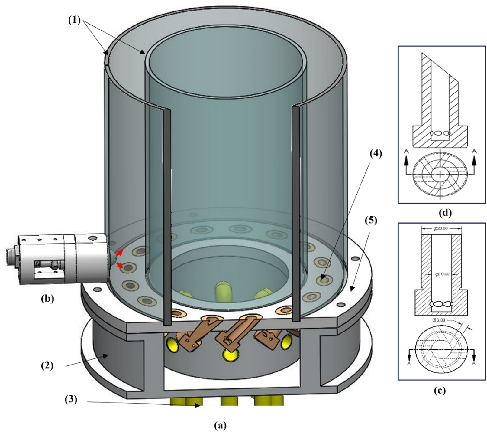
Schematic of the experimental arrangement, (A) The combustor; (1) Quartz tubes; (2) Plenum; (3) Supplying pipes; (4) Swirl burner; (5) Annular plate, (B) Pre-chamber, (C) Straight burner configuration, (D) Oblique burner configuration.
The pre-chamber used for the current experiment has two orifices, each 5 mm in diameter. The pre-chamber tip is mounted through a hole in the outer glass tube, as shown in Figure 1B. According to this arrangement, the jets issued from the pre-chamber will be directed to the center of the two adjacent burners, as depicted in Figure 2B. Propane fuel is delivered to the pre-chamber through a gas injector, and the combustion is initiated by a J-type spark plug with a gap of 1 mm. Additional details regarding the experimental test rig are available in the previous work [21, 33].
FIGURE 2
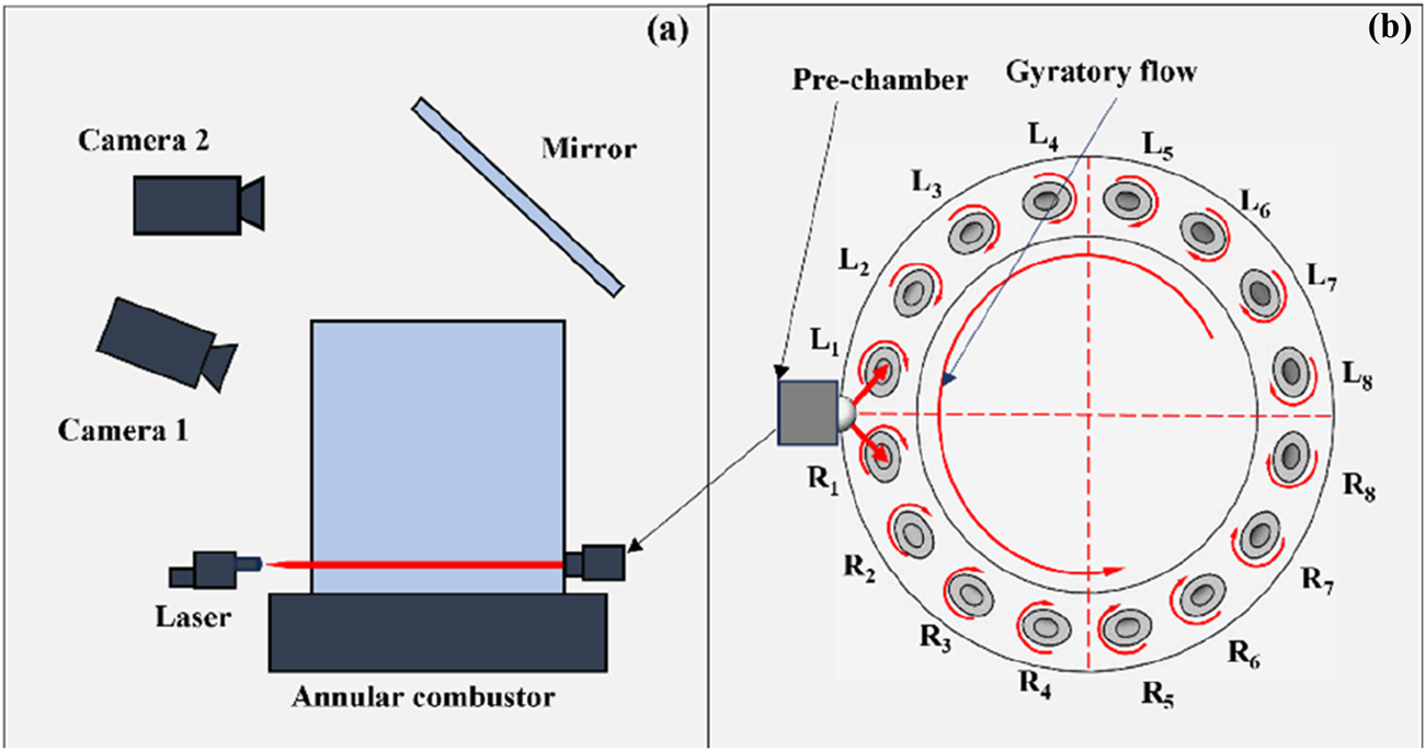
Setup of the diagnostics layout (A) and the swirl burners configuration (B).
The diagnostic layout is shown in Figure 2A. The visualization process consists of two synchronized cameras (FASTCAM Nova S16) to record the flame propagation patterns from the vertical and horizontal planes. The frame speed is set at 4000 fbs with an exposure time of and Pixel resolution. For better flame recording, a UV-IR cut filter with a visible bandpass of 400∼680 nm is integrated into the camera lens. The cameras are triggered simultaneously at the spark activation instance in the pre-chamber ignitor.
The experimental work for both combustors is divided into four group tests, as shown in Table 1. The fuel volume flow rate (Qf) is 10, 12, 14, and 16 L/minute. Each fuel flow rate has five different air volume flow rates (Qa), and the equivalence ratio varies from ϕ = 0.67 to ϕ = 0.85. The bulk velocity for each swirl injector varies from Ub = 3.9 m/s to Ub = 6.2 m/s, and thermal power P = 15.5 kW to P = 24.8 kW. Through Camera 2, the flame front position is estimated using Mie scattering, achieved with a frame rate of 10,000 fps. DEHS aerosol particles are injected into the inlet of the annular combustor along with the air-fuel mixture, and these particles are illuminated by a continuous laser diode, as shown in Figure 5. The particles are seeded into the combustor using 2% of the inlet airflow. This minimal percentage ensures that the equivalence ratio remains unaffected. Additionally, the oil particles quickly evaporate as the flame reaches the region of interest. This strategy is highly effective in estimating the flame position during the ignition process in the annular combustor. The injected oil particles initially appear as a gray color, representing the unburnt region before the flame reaches that point. Once the flame arrives, the oil particles are burnt, resulting in a black region that represents the burnt area. A MATLAB code is then used to postprocess the frames distinguishing between the two regions and identifying the flame front [34].
TABLE 1
|
L/m |
L/m |
ϕ (−) | P kW | Ub m/s |
|---|---|---|---|---|
| 10 | 357 | 0.67 | 15.5 | 4.9 |
| 10 | 342 | 0.7 | 15.5 | 4.67 |
| 10 | 319 | 0.75 | 15.5 | 4.37 |
| 10 | 299 | 0.8 | 15.5 | 4.1 |
| 10 | 282 | 0.85 | 15.5 | 3.87 |
| 12 | 428 | 0.67 | 18.6 | 5.85 |
| 12 | 410 | 0.7 | 18.6 | 5.6 |
| 12 | 383 | 0.75 | 18.6 | 5.24 |
| 12 | 359 | 0.8 | 18.6 | 4.92 |
| 12 | 338 | 0.85 | 18.6 | 4.64 |
| 14 | 500 | 0.67 | 21.7 | 6.82 |
| 14 | 479 | 0.7 | 21.7 | 6.54 |
| 14 | 447 | 0.75 | 21.7 | 6.11 |
| 14 | 419 | 0.8 | 21.7 | 5.74 |
| 14 | 394 | 0.85 | 21.7 | 5.42 |
| 16 | 572 | 0.67 | 24.8 | 7.8 |
| 16 | 547 | 0.7 | 24.8 | 7.47 |
| 16 | 511 | 0.75 | 24.8 | 6.99 |
| 16 | 479 | 0.8 | 24.8 | 6.56 |
| 16 | 451 | 0.85 | 24.8 | 6.19 |
Experimental data.
The experimental procedures are arranged as follows:
1. Propane fuel is mixed with air before being delivered into the annular combustor. This process starts by opening the airflow controller with a specific range, followed by opening the fuel flow controller.
2. The combustion sequence is initiated in the pre-chamber by injecting fuel by the gas injector. Then, the spark is activated. In this instance, the high-speed cameras are triggered, and the ignition occurs in the annular combustor.
3. The test is repeated using different equivalence ratios and thermal power.
4. The annular combustor’s oblique-injecting burner replaces the straight-injecting burner, and the test is conducted using the same operating procedures.
5. After each test, flush air is pumped into the pre-chamber combustion chamber to remove the combustion products, and each test is repeated at least three times.
Results
This section describes the flame propagation patterns of the oblique-injecting annular combustor using the pre-chamber ignitor and compares its performance with that of the straight-injecting one. Both combustors are tested under the same conditions and operating parameters.
Ignition Process
In this study, pre-chamber was implemented in the oblique- and straight-injecting annular combustors to initiate the ignition process. The chemiluminescence images of the flame propagation process of the two combustor types are shown in Figures 3, 4 and it have been enhanced with a gradient color bar, where black represents the lowest light intensity and yellow indicates the highest light intensity. The ignition relies on gases generated within the pre-chamber, expelled as hot jets and rapidly directed to the mixture in the annular combustor. As shown in Figure 3 at time 16 ms, two flame jets are released towards the oblique-injecting combustor, while Figure 4 depicts the annular combustor with straight-injecting burners. From the second frame at t = 17 ms to t = 23 ms, the flame extends along both sides of the annular combustors. The flame patterns indicate that the ignition process in both annular combustors is highly dependent on the trajectory of the burning jets, which increases the burning rate due to the numerous ignition points created along the jet’s trajectories. The propagating jet from the pre-chamber also helps push part of the flame towards the fresh mixture in the annular combustors, further increasing the burning rate and reducing the light-round time. Conversely, conventional ignition methods using a spark electrode ignitor depend on a small flame kernel formed at the spark electrode [35].
FIGURE 3
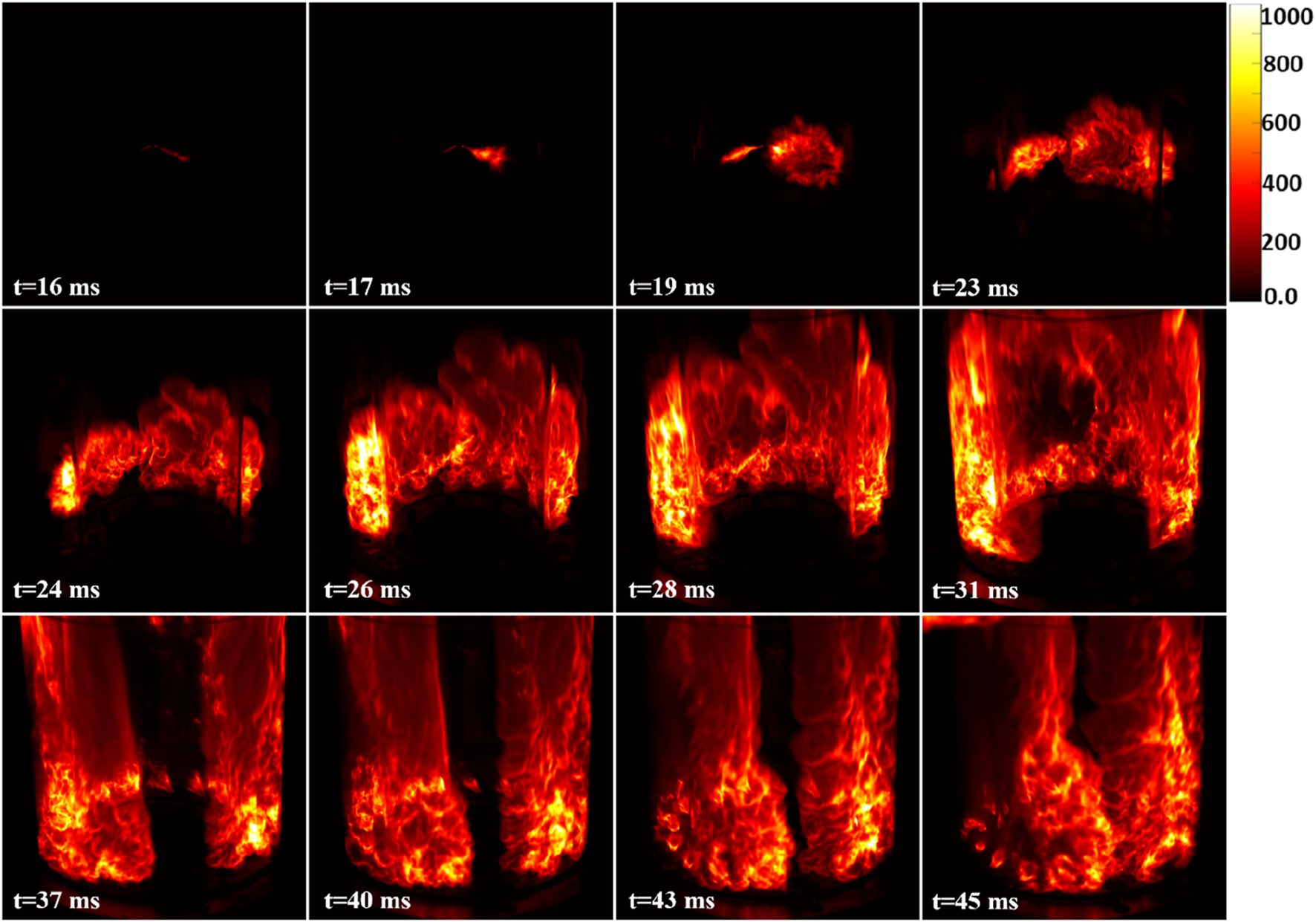
The light-round sequences of the oblique annular combustor using a pre-chamber ignitor (ϕ = 0.7, P = 18.6 kW). The chemiluminescence image has been enhanced with a gradient color bar, where black represents the lowest light intensity and yellow indicates the highest light intensity.
FIGURE 4
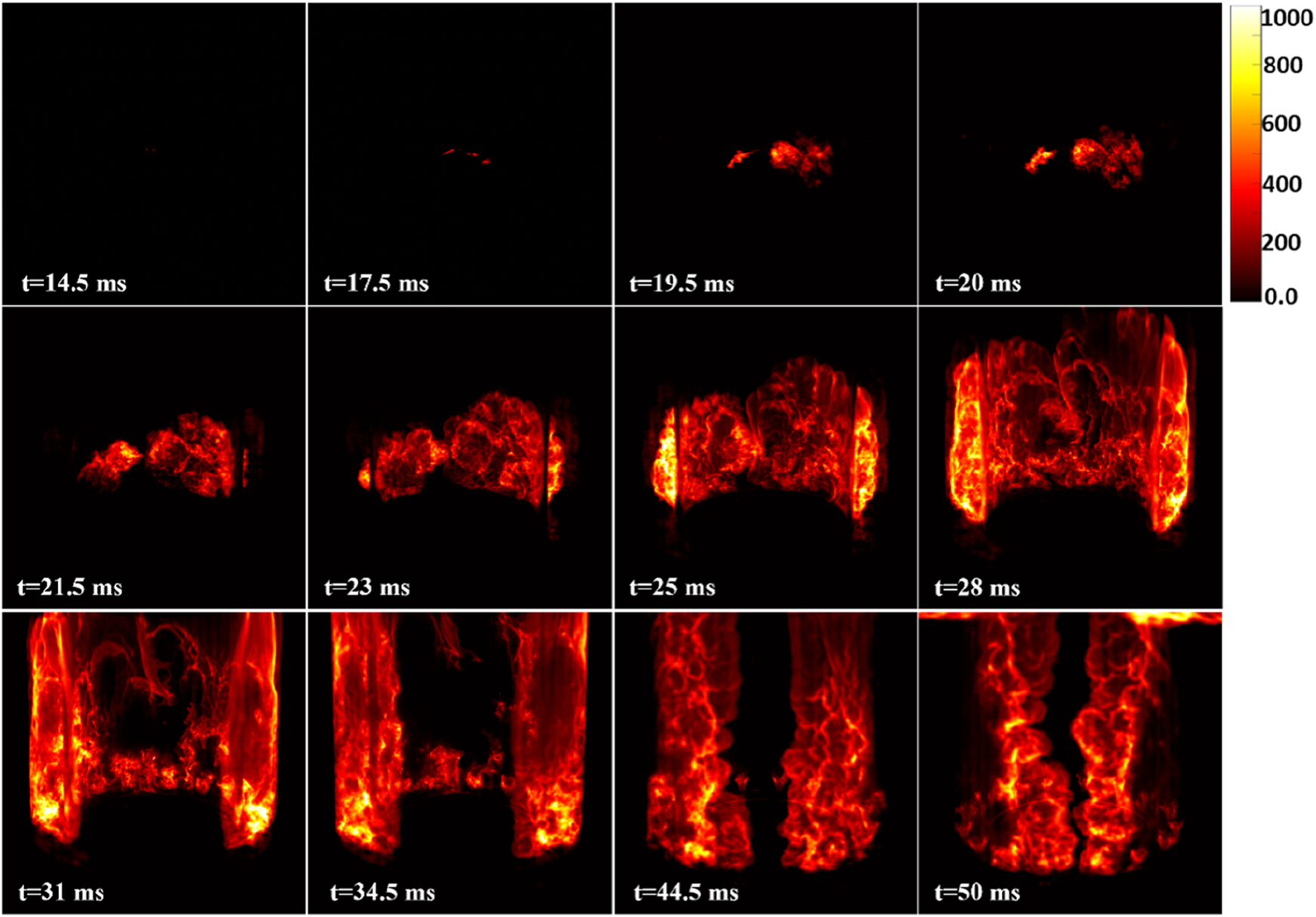
The light-round sequences of the straight annular combustor using a pre-chamber ignitor (ϕ =0.7, P = 18.6 kW), The chemiluminescence image has been enhanced with a gradient color bar, where black represents the lowest light intensity and yellow indicates the highest light intensity.
In the case of straight-injection combustors, the two flame branches remain symmetrical until they merge between burners (R8, L8). However, in the oblique-injecting combustor, the gyratory flow motion of the fresh mixture affects the flame spread process. This is evident in frames obtained by the high-speed camera; these fluid movements help carry the flame patterns on the right side, shifting the merging point slightly away from the combustor midpoint. Despite the asymmetry of the jet released from the pre-chamber, where the first three frames for the two combustors show a stronger jet on the left side due to the combustion process inside the pre-chamber, this phenomenon reduces the side effects of gyratory flow motion in the initial stages of ignition, thereby increasing the burning rate on the right side in the oblique-injecting combustor. Although the oblique-injecting burner enhances the mixing process before ignition, it causes asymmetry in flame patterns on both sides of the annular combustor, especially with traditional ignition methods. This phenomenon is consistent with previous results that show that the pre-chamber reduces the asymmetry of the light-round process [21].
The flame positions during jet propagation for both combustors are illustrated in Figure 5 where the red color denotes the flame front, effectively distinguishing the burnt and unburnt regions. For both combustors, the ignition process along the trajectories of the jet flames shows no significant differences in the burnt regions on either side of the annular combustor. Additionally, the propagating jets generate multiple ignition points along their trajectories, increasing the probability of ignition success and enhancing the circumferential flame propagation speed within the combustor. In contrast to a traditional spark electrode [35], where the flame development relies on the initial kernel formed near the electrode site, the pre-chamber ignitor exhibits a more distributed and robust ignition mechanism. This observation highlights the effectiveness of the pre-chamber ignitor under various ignition conditions.
FIGURE 5
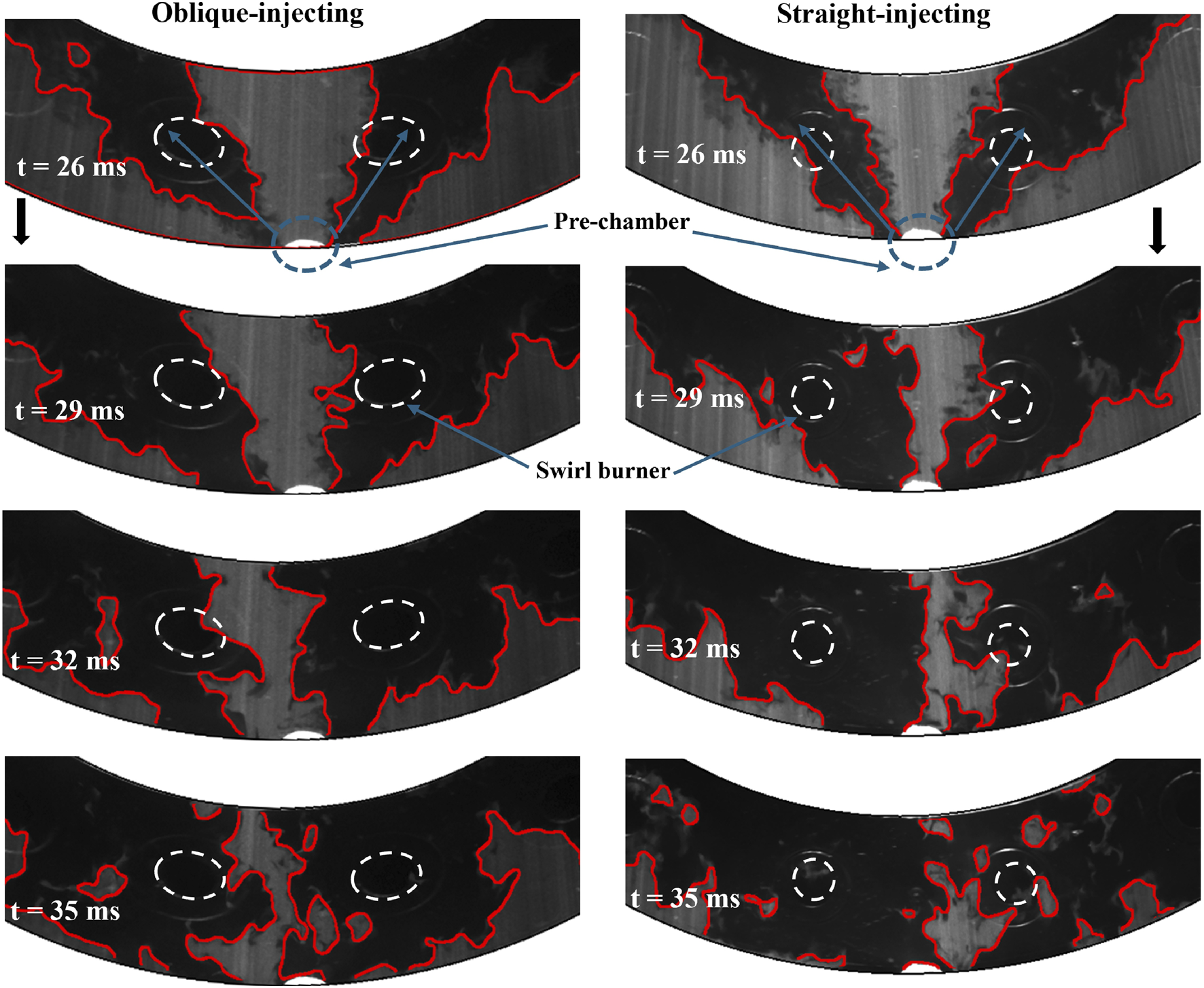
Flame front position during jet propagation near the pre-chamber for both combustors. The dark regions represent the burning zones, while the grey areas indicate unburned regions. The red lines mark the flame front.
The effectiveness of pre-chamber ignition in the oblique combustor is evident from t = 26 ms to t = 29 ms, where jet flame propagation plays a dominant role in the ignition process. The influence of the gyratory flow motion induced by the obliquely injected burner is relatively minimal. Notably, in both the oblique and straight injection configurations, the propagating jets drive hot gases from the pre-chamber outlet towards the inner tube. This redistribution enhances the burning rate in these areas, contributing significantly to the light-round process by reducing light-round time, since the leading point of the flame propagation is closer to the inner tube facilitating faster flame expansion [35]. This phenomenon highlights the critical role of jet-driven ignition in promoting efficient combustion, particularly in annular combustor designs with varied injection strategies.
The corresponding integrated light intensity values of the ignition processes are shown in Figures 6, 7. Figures 6A, B compare the intensity values of the oblique-injecting and straight-injecting combustors with varying equivalence ratios while maintaining constant power. The integrated light intensity is obtained by summing the intensity values of all pixels in each image captured by the high-speed camera throughout the recording period. For both annular combustors, when the jets appear, the intensity values increase rapidly as the flame spreads in the combustors. Similarly, the light intensity increases in the previous work, and the spark electrode discharges ignition energy near the swirl burner (L1), forming the initial flame kernel around the ignition location [4]. Increasing the equivalence ratio led to a higher fuel supply to the combustor and a higher laminar flame speed, directly increasing the integrated light intensity. The values of integrated light intensity with constant equivalence ratio and different thermal powers are shown in Figure 7 for both combustors. With an increase in fluid velocity, the burning rate in the combustor increases as fluid movements help carry flame patterns more quickly toward the merging point. In higher thermal power cases, the illumination intensity is higher than the ones of lower thermal power for both combustors. In general, there are some differences in the intensity between the oblique-injecting and the straight-injecting combustors, this may be attributed to a slight deviation in the camera recording angle from its previous position [4].
FIGURE 6
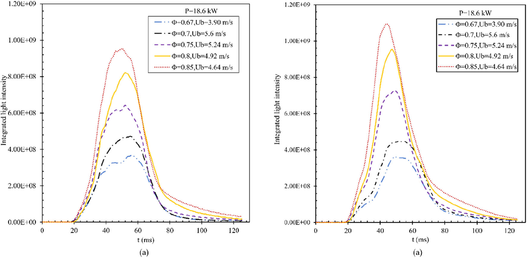
Integrated light intensity for both combustors at constant thermal power (P = 18.6 kW) and different equivalence ratios using pre-chamber ignitor. (A) Oblique-injecting combustor. (B) Straight-injecting combustor.
FIGURE 7
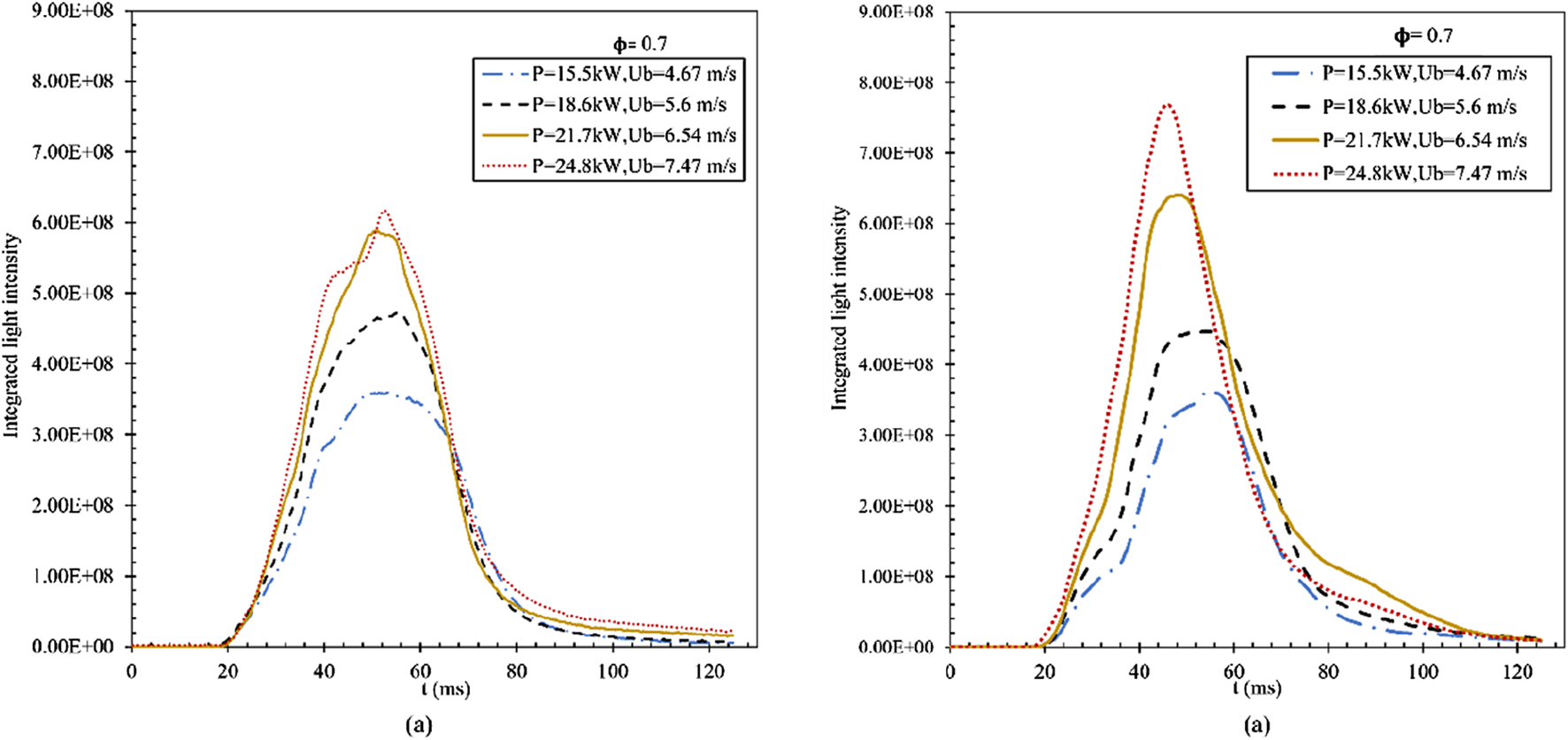
Integrated light intensity for both combustors at constant equivalence ratio (ϕ = 0.7) and different thermal power using pre-chamber ignitor. (A) Oblique-injecting combustor. (B) Straight-injecting combustor.
Light Round Time
The ignition process in aircraft engines must be carried out quickly and safely. Therefore, the light-round time () is considered one of the most critical factors determining the effectiveness of the ignition method and its suitability for different operating conditions. The light-round time is known as the time elapsed from the appearance of the first flame kernel until the merging of the two flame sides in the annular combustor [4].
Figures 8A, B compares the values of light-round time using a pre-chamber and spark electrode for both combustors. The pre-chamber improved the combustion characteristics, which increased the burning rate for both combustors. Consequently, this has led to a reduction in the light-round time compared to traditional ignition methods. Generally, with constant thermal power and increasing air mass flow rate, where the equivalence ratio decreases, the ignition time increases. As mentioned in [36] the time needed to ignite the first burner in the combustor is increased if the flow velocity increases. It should be noted that the reference time for estimating the light-round time differs between the pre-chamber and the traditional spark ignitor methods. In the traditional method, the initial time is defined as the moment when the first successful flame kernel forms, with the spark discharge duration increasing if the mixture in the annular combustor is leaner. In contrast, for the pre-chamber, the initial time is set at the moment the spark is activated. This leads to the difference in the light-round time using the pre-chamber, which is much greater than the traditional method if the spark discharge duration is considered. This explains the difference in the light-round time at low bulk velocities, as shown in Figure 8B. At high bulk velocities, where the values of the equivalence ratios are small, the traditional ignition method requires a longer time to form an initial flame kernel, which affects the flame propagation process in the combustors. In addition, some studies have observed that the spark electrode continues to discharge energy throughout the light-round process [10]. This is in contrast to the pre-chamber, which significantly reduces the ignition time in these conditions. This results in the flame issued from the pre-chamber being less dependent on the local air-fuel mixture inside the annular combustor. The pre-chamber is effectively isolated from surrounding influences, making it a more reliable ignition source across various operating conditions. In contrast, the traditional spark electrode relies directly on the local mixture to initiate the flame during the engine lighting process, making it more sensitive to variations in the combustor environment [21].
FIGURE 8
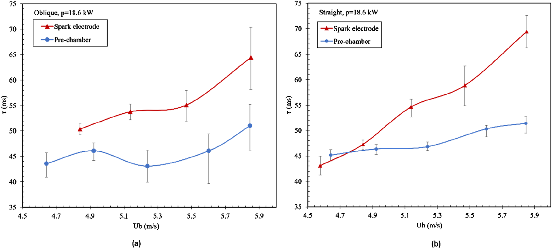
Light-round time τ at P = 18.6 kW for both annular combustors using spark electrode and pre-chamber ignitors. Electrode ignitor from work in [4]. (A) Oblique-injecting combustor. (B) Straight-injecting combustor.
Figure 9 illustrates the light-round contour for both combustors at varying equivalence ratios and thermal powers, utilizing a pre-chamber ignitor. The straight combustor displays smoother transient results, while the oblique combustor shows an increase in light-round time at higher thermal power levels associated with a higher equivalence ratio. This behavior may be attributed to the higher bulk velocity, which adversely affects flame propagation by quenching part of the flame kernels. Generally, longer light-round times are observed at lower equivalence ratios, which are also linked to lower thermal powers. With constant thermal power, raising the equivalence ratio considerably decreases the light-round time, owing to the faster laminar flame speed. Similarly, at a constant equivalence ratio, increasing the thermal power decreases the light-round time, as enhanced flow motion aids in carrying flame front over longer distances.
FIGURE 9
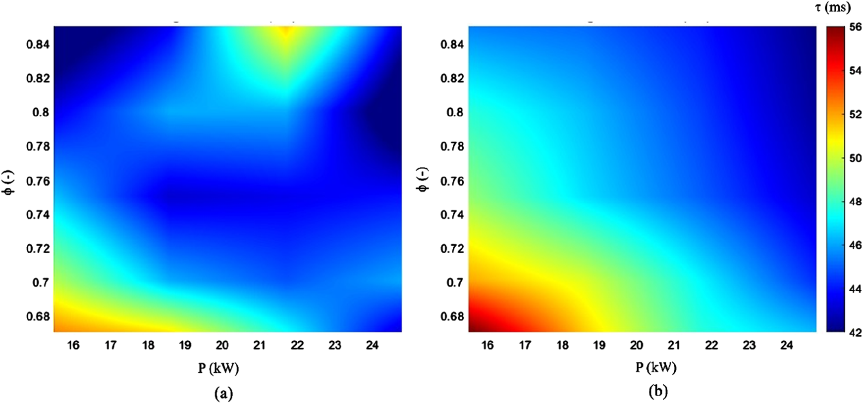
Contour for the light-round time (τ) for both annular combustors using a pre-chamber ignitor. (A) Oblique-injecting combustor. (B) Straight-injecting combustor.
Light Round Sequence
During the aero engine lighting process, the flame moves from one burner to the adjacent one in the annular combustor until the last burner is ignited. Figure 10A, B depict the flame position during the ignition process for the oblique-injecting and straight-injecting combustors at a fixed equivalence ratio of ϕ = 0.7 and different thermal power. The pre-chamber ignitor significantly increases the burning rate, especially at the early stages for the burners near the pre-chamber orifices, as shown in Figure 10 for both combustors. Figures 11A, B shows the flame position during the light-round time at constant thermal power and different equivalence ratios for the two combustors. In Figure 11B, the straight-injecting combustor features more symmetry in flame propagation, unlike the oblique-injecting combustor. The phenomenon of oblique injection affects the symmetry of flame propagation, although it reduces light-round time in most cases. It also greatly affected the merging flame position, where the merging point in the case of a straight-injecting combustor is often at an angle of 180°. At the same time, it is slightly shifted for the oblique-injecting combustor.
FIGURE 10
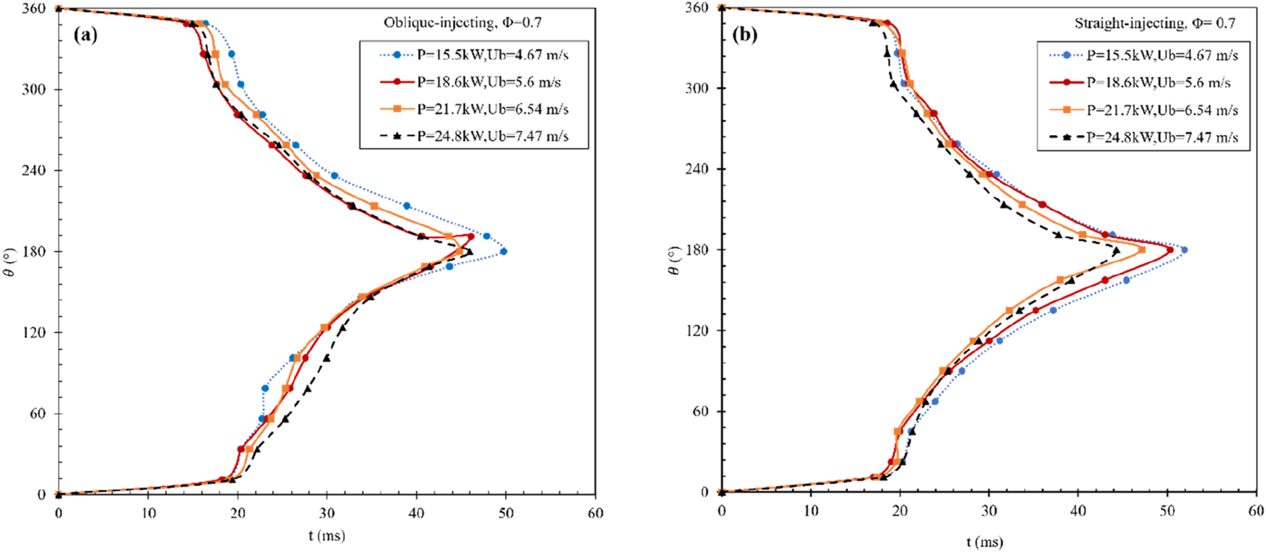
Variation of flame position with time at fixed equivalence ratio (Φ = 0.7) and different thermal power using a pre-chamber ignitor for both combustors: (a) oblique-injecting combustor and (b) straight-injecting combustor.
FIGURE 11
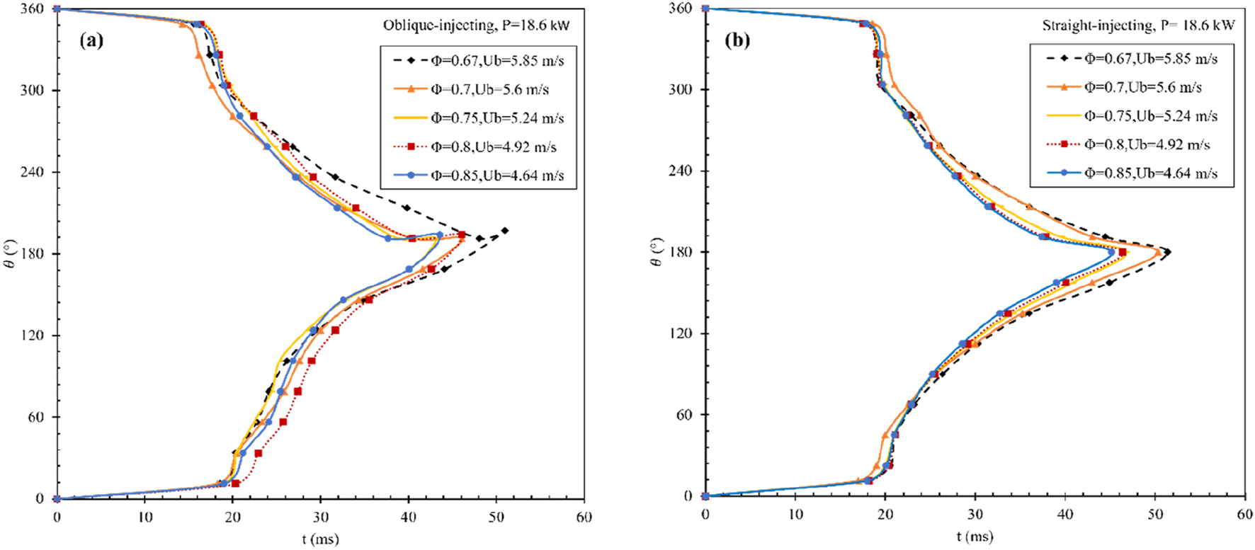
Variation of flame position with time at fixed power (P = 18.6 kW) and different equivalence ratios using a pre-chamber ignitor for both combustors: (a) oblique-injecting combustor and (b) straight-injecting combustor.
The circumferential velocity can be calculated from Equation 1, where is the covered angle by the flame, R is the combustor radius, and is the time difference [18].
Figures 12, 13 show the average circumferential velocity of both sides of the flame and the difference ( between them for both combustors. The bulk velocity generally influences the circumferential speed in the annular combustor. As the bulk velocity increases, the circumferential speed also rises since the higher flow velocity aids in transporting the flame to adjacent burners. Additionally, an increase in the equivalence ratio directly boosts the circumferential speed due to the higher laminar flame speed. The circumferential speed value is calculated from 45° to 315°, where the speeds are more stable at this stage. The circumferential velocity using the oblique-injecting burner is greater than that of the straight one. This is attributed to the swirling fluid motions in the circumferential direction in the cold flow field before ignition. The figures show that the gyratory flow motion from the oblique-injecting burners affects the flame’s circumferential velocity on both sides. The difference ( is significant in the oblique-injecting combustor. While the difference is much smaller in the straight-injecting one, as shown in Figures 12, 13.
FIGURE 12
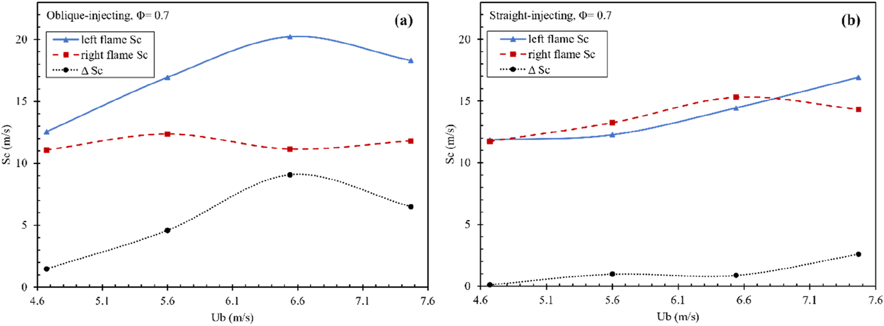
Circumferential speed using pre-chamber for the left and right flames at constant equivalence ratio (ϕ = 0.7) and their differences in (A) oblique-injecting combustor, (B) straight-injecting combustor.
FIGURE 13
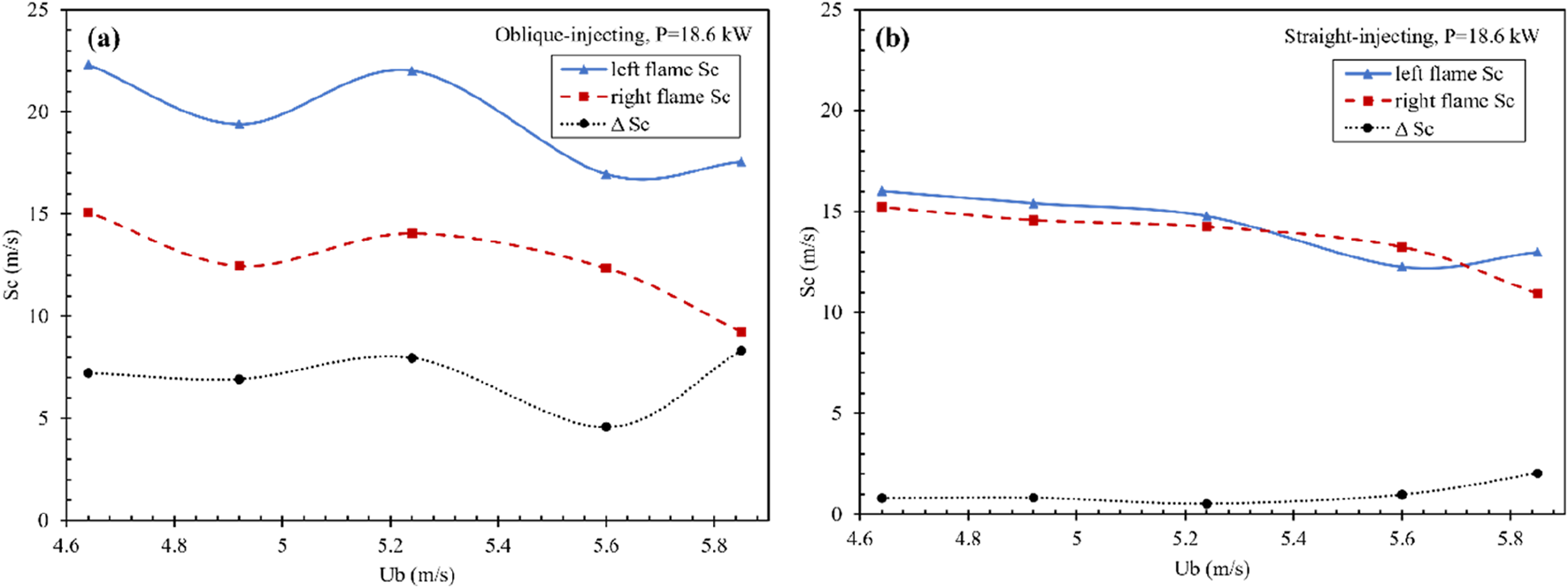
Circumferential speed using pre-chamber for the left and right flames at constant thermal power (P = 18.6 kW) and their differences in (A) oblique-injecting combustor, (B) straight-injecting combustor.
Conclusion
This study innovatively investigated the ignition dynamics and light-round process of the oblique-injecting combustor using a pre-chamber ignitor. Compared to the conventional spark electrode, the pre-chamber generated a strong turbulent jet, creating multiple successful ignition sites that enhanced ignition properties, prevented misfiring, and improved the light-round process in both oblique and straight-injecting combustors. Different experimental tests were conducted and monitored via high-speed cameras across various equivalence ratios and thermal power levels for the oblique-injecting combustor and compared to the straight-injecting combustor at the same operating conditions. The flame position during the ignition sequence is recorded using the Mie scattering method.
The following conclusions can be drawn:
• The integration of the pre-chamber ignition system into the oblique-injecting combustor reduced flame asymmetry on both sides, which is caused by the gyratory flow motion before ignition. Mie scattering analysis indicates that during the early stages of ignition in the oblique-injecting combustor, the burning rate is approximately equal on both sides of the combustor.
• The pre-chamber ignitor exhibits great effectiveness for both combustors at low equivalence ratios, which makes the pre-chamber the optimum solution for different ignition conditions. In contrast, the conventional spark electrode ignitor requires a longer discharge time to initiate the ignition process in the combustor.
• The propagating jets from the pre-chamber enhance the burning rate in both combustors by generating initial flame kernels along the jet’s trajectory. This accelerates flame propagation in the circumferential direction, thereby reducing the light-round time.
Statements
Data availability statement
The original contributions presented in the study are included in the article/supplementary material, further inquiries can be directed to the corresponding authors.
Author contributions
HH: Writing–original draft, Validation, Methodology, Investigation, Formal analysis, Data curation. CQ: Formal analysis. HW: Writing–review and editing, Formal analysis. JZ: Writing–review and editing. HG: Supervision, Investigation, Data curation, Conceptualization. EB: Writing–review and editing, Methodology, Formal analysis. GW: Validation, Supervision, Project administration, Methodology, Funding acquisition, Conceptualization. All authors contributed to the article and approved the submitted version.
Funding
The author(s) declare that financial support was received for the research and/or publication of this article. This work was supported by the National Science and Technology Major Project (No. J2019-III-0006-0049) and National Natural Science Foundation of China (No. U2341282).
Conflict of interest
The authors declare that the research was conducted in the absence of any commercial or financial relationships that could be construed as a potential conflict of interest.
Generative AI statement
The author(s) declare that no Generative AI was used in the creation of this manuscript.
References
1.
Liu C Yang H Li X Yu L Lu X . Experimental Study on the Impact of Swirl Configurations and Ammonia-Methane Blends on the Ignition Dynamics of a Premixed Annular Combustor. Fuel (2025) 389:134583. 10.1016/j.fuel.2025.134583
2.
Abdulrahman GAQ Qasem NAA Imteyaz B Abdallah AM Habib MA . A Review of Aircraft Subsonic and Supersonic Combustors. Aerosp Sci Technol (2023) 132:108067. 10.1016/j.ast.2022.108067
3.
Gao W Wang S Liu F Mu Y Wang K Zhu J et al Comparison of Ignition Characteristics Between Annular and Multi-Sector Combustor. J Energy Inst (2022) 104:55–66. 10.1016/j.joei.2022.06.007
4.
Wang G Zhong L Yang Y Zheng Y Fang Y Xia Y et al Experimental Investigation of the Ignition Dynamics in an Annular Premixed Combustor with Oblique-Injecting Swirling Burners. Fuel (2021) 287:119494. 10.1016/j.fuel.2020.119494
5.
Ciardiello R Skiba AW Gordon RL Mastorakos E . Experimental Assessment of the Lean Blow-Off in a Fully Premixed Annular Combustor. Exp Therm Fluid Sci (2020) 112:109994. 10.1016/j.expthermflusci.2019.109994
6.
Ye C Wang G Fang Y Ma C Zhong L Moreau S . Ignition Dynamics in an Annular Combustor with Gyratory Flow Motion. Turbo Expo Power Land, Sea, Air (2018) 51067:V04BT04A030.
7.
Al-Abdeli YM Masri AR . Review of Laboratory Swirl Burners and Experiments for Model Validation. Exp Therm Fluid Sci (2015) 69:178–96. 10.1016/j.expthermflusci.2015.07.023
8.
An Y Shen S Fu X Wang Y Pei Y Zhang Y et al Effects of Inlet Air Holes on Swirl Flow Characteristics and Outlet Temperature Distribution in an Axial Swirl Combustor. Case Stud Therm Eng (2024) 61:105085. 10.1016/j.csite.2024.105085
9.
Khandelwal B Lili D Sethi V . Design and Study on Performance of Axial Swirler for Annular Combustor by Changing Different Design Parameters. J Energy Inst (2014) 87:372–82. 10.1016/j.joei.2014.03.022
10.
Bourgouin JF Durox D Schuller T Beaunier J Candel S . Ignition Dynamics of an Annular Combustor Equipped with Multiple Swirling Injectors. Combust Flame (2013) 160:1398–413. 10.1016/j.combustflame.2013.02.014
11.
Philip M Boileau M Vicquelin R Riber E Schmitt T Cuenot B et al Large Eddy Simulations of the Ignition Sequence of an Annular Multiple-Injector Combustor. Proc Combust Inst (2015) 35:3159–66. 10.1016/j.proci.2014.07.008
12.
Philip M Boileau M Vicquelin R Schmitt T Durox D Bourgouin JF et al Simulation of the Ignition Process in an Annular Multiple-Injector Combustor and Comparison with Experiments. J Eng Gas Turbine Power (2015) 137:031501. 10.1115/1.4028265
13.
Machover E Mastorakos E . Experimental Investigation on Spark Ignition of Annular Premixed Combustors. Combust Flame (2017) 178:148–57. 10.1016/j.combustflame.2017.01.013
14.
Machover E Mastorakos E . Spark Ignition of Annular Non-premixed Combustors. Exp Therm Fluid Sci (2016) 73:64–70. 10.1016/j.expthermflusci.2015.09.008
15.
Mansour MS Elbaz AM Samy M . The Stabilization Mechanism of Highly Stabilized Partially Premixed Flames in a Concentric Flow Conical Nozzle Burner. Exp Therm Fluid Sci (2012) 43:55–62. 10.1016/j.expthermflusci.2012.03.017
16.
Barakat S Wang H Jin T Tao W Wang G . Isothermal Swirling Flow Characteristics and Pressure Drop Analysis of a Novel Double Swirl Burner. AIP Adv (2021) 11:035240. 10.1063/5.0041361
17.
Wang G Wang H Xia Y Zhong L Barakat E Tao W . Flame Propagation Patterns and Local Flame Features of an Annular Combustor with Multiple Centrally Staged Swirling Burners. Phys Fluids (2023) 35:085134. 10.1063/5.0165269
18.
Wang H Zhong L Barakat E Xia Y Tao W Tong X et al Experimental Investigation on the Ignition Dynamics of an Annular Combustor with Multiple Centrally Staged Swirling Burners. Phys Fluids (2022) 34:0095756. 10.1063/5.0095756
19.
Wang H Zhu Z Barakat E Hou J Hassan H Liu J et al Investigation of Flow Interaction and the Impact on Flame Propagation in an Annular Combustor with Centrally Staged Burners. Fuel (2025) 390:134694. 10.1016/j.fuel.2025.134694
20.
Qian C Yang Y Zhu Z Hu K Hassan H Krikunova A et al A Comprehensive Investigation on Flame Flickering Characteristics of Premixed Conical Flame at Different Inclination Angles. Combust Flame (2024) 269:113644. 10.1016/j.combustflame.2024.113644
21.
Hassan H Hu K Qian C Wang H Ge H Wang G et al Enhancing Ignition Stability in an Annular Combustor Using a Pre-chamber Ignition System. Appl Therm Eng (2025) 258:124501. 10.1016/j.applthermaleng.2024.124501
22.
Gussak LA Karpov VP Tikhonov YV . The Application of Lag-Process in Prechamber Engines. In: SAE Technical Paper (1979).790692.
23.
Chen H Li Y Jiang X Du J Li Y Zhan W . Experimental Study on Gasoline-Ammonia Combustion Characteristics with Pre-chamber Jet Ignition. J Energy Inst (2023) 111:101429. 10.1016/j.joei.2023.101429
24.
Gentz G Thelen B Gholamisheeri M Litke P Brown A Hoke J et al A Study of the Influence of Orifice Diameter on a Turbulent Jet Ignition System through Combustion Visualization and Performance Characterization in a Rapid Compression Machine. Appl Therm Eng (2015) 81:399–411. 10.1016/j.applthermaleng.2015.02.026
25.
Ge H Bakir AH Yadav S Kang Y Parameswaran S Zhao P . CFD Optimization of the Pre-chamber Geometry for a Gasoline Spark Ignition Engine. Front Mech Eng (2021) 6:599752. 10.3389/fmech.2020.599752
26.
Muller M Freeman C Zhao P Ge H . Numerical Simulation of Ignition Mechanism in the Main Chamber of Turbulent Jet Ignition System. In: ASME Internal Combustion Engine Division Fall Technical Conference, 51999 (2018). V002T06A010.
27.
Huang S Li T Chen R Yi P Li S Wang X et al Computational Analysis of the Scavenging Characteristic and Optimization of Passive Pre-chamber. Appl Therm Eng (2024) 243:122676. 10.1016/j.applthermaleng.2024.122676
28.
Lv Y Feng S Luo J Liu Q Li L Kang Z . Effect of Key Structure Parameters of Passive Pre-chamber on In-Cylinder Combustion Processes and Emissions within a Gasoline Engine. Case Stud Therm Eng (2024) 59:104467. 10.1016/j.csite.2024.104467
29.
Wang Z Ji C Wang D Zhang T Wang S Yang H et al Experimental Investigation on Combustion Characteristics of Ammonia/air Using Turbulent Jet Ignition with Auxiliary Oxygen in Pre-chamber. Appl Therm Eng (2024) 243:122622. 10.1016/j.applthermaleng.2024.122622
30.
Kang Z Peng D Luo J Lv Y Li L . Effect of Structural Parameters of Active Pre-chamber on Ammonia/hydrogen Premixed Combustion Process: A Numerical Investigation. Case Stud Therm Eng (2025) 65:105687. 10.1016/j.csite.2024.105687
31.
Trombley G Toulson E . A Fuel-Focused Review of Pre-chamber Initiated Combustion. Energy Convers Manag (2023) 298:117765. 10.1016/j.enconman.2023.117765
32.
Zhu S Akehurst S Lewis A Yuan H . A Review of the Pre-chamber Ignition System Applied on Future Low-Carbon Spark Ignition Engines. Renew Sustain Energy Rev (2022) 154:111872. 10.1016/j.rser.2021.111872
33.
Hassan H Wang H Barakat E Qian C Ge H Zhu Z et al Experimental Investigation of the Ignition Dynamics in a Premixed Annular Combustor Using a Pre-chamber Ignition System. Energy Convers Manage: X (2024) 24:100754. 10.1016/j.ecmx.2024.100754
34.
Zhong L Yang Y Jin T Xia Y Fang Y Zheng Y et al Local Flame and Flow Properties of Propagating Premixed Turbulent Flames during Light-Round Process in a MICCA-type Annular Combustor. Combust Flame (2021) 231:111494. 10.1016/j.combustflame.2021.111494
35.
Xia Y Linghu C Zheng Y Ye C Ma C Ge H et al Experimental Investigation of the Flame Front Propagation Characteristic during Light-Round Ignition in an Annular Combustor. Flow Turbul Combust (2019) 103:247–69. 10.1007/s10494-019-00018-y
36.
Bach E Kariuki J Dawson JR Mastorakos E Bauer HJ . Spark Ignition of Single Bluff-Body Premixed Flames and Annular Combustors. In: 51st AIAA Aerospace Sciences Meeting Including the New Horizons Forum and Aerospace Exposition 2013. American Institute of Aeronautics and Astronautics Inc. (2013). 1–12. 10.2514/6.2013-1182
Summary
Keywords
pre-chamber, oblique-injecting, annular combustor, ignition characteristics, light-round
Citation
Hassan H, Qian C, Wang H, Zhu J, Ge H, Barakat E and Wang G (2025) Experimental Study of Ignition Characteristics in Oblique-Injected Annular Combustors Using a Pre-Chamber Ignition System. Aerosp. Res. Commun. 3:14383. doi: 10.3389/arc.2025.14383
Received
23 January 2025
Accepted
20 March 2025
Published
27 March 2025
Volume
3 - 2025
Updates
Copyright
© 2025 Hassan, Qian, Wang, Zhu, Ge, Barakat and Wang.
This is an open-access article distributed under the terms of the Creative Commons Attribution License (CC BY). The use, distribution or reproduction in other forums is permitted, provided the original author(s) and the copyright owner(s) are credited and that the original publication in this journal is cited, in accordance with accepted academic practice. No use, distribution or reproduction is permitted which does not comply with these terms.
*Correspondence: Haiwen Ge, gehaiwen@zhejianglab.org; Gaofeng Wang, gfwang@zju.edu.cn
Disclaimer
All claims expressed in this article are solely those of the authors and do not necessarily represent those of their affiliated organizations, or those of the publisher, the editors and the reviewers. Any product that may be evaluated in this article or claim that may be made by its manufacturer is not guaranteed or endorsed by the publisher.